00192662-01.pdf - 第225页
User Manual SIPLAC E F5/F5 HM 6 Vision functions Software version SR.407.xx 01/2001 US Edition 6.1 The vision systems on the placement machine 225 The co mponen t camer a syste m is fixe d to th e top o f the Coll ect&am…
6 Vision functions User Manual SIPLACE F5/F5 HM
6.1 The vision systems on the placement machine Software version SR.407.xx 01/2001 US Edition
224
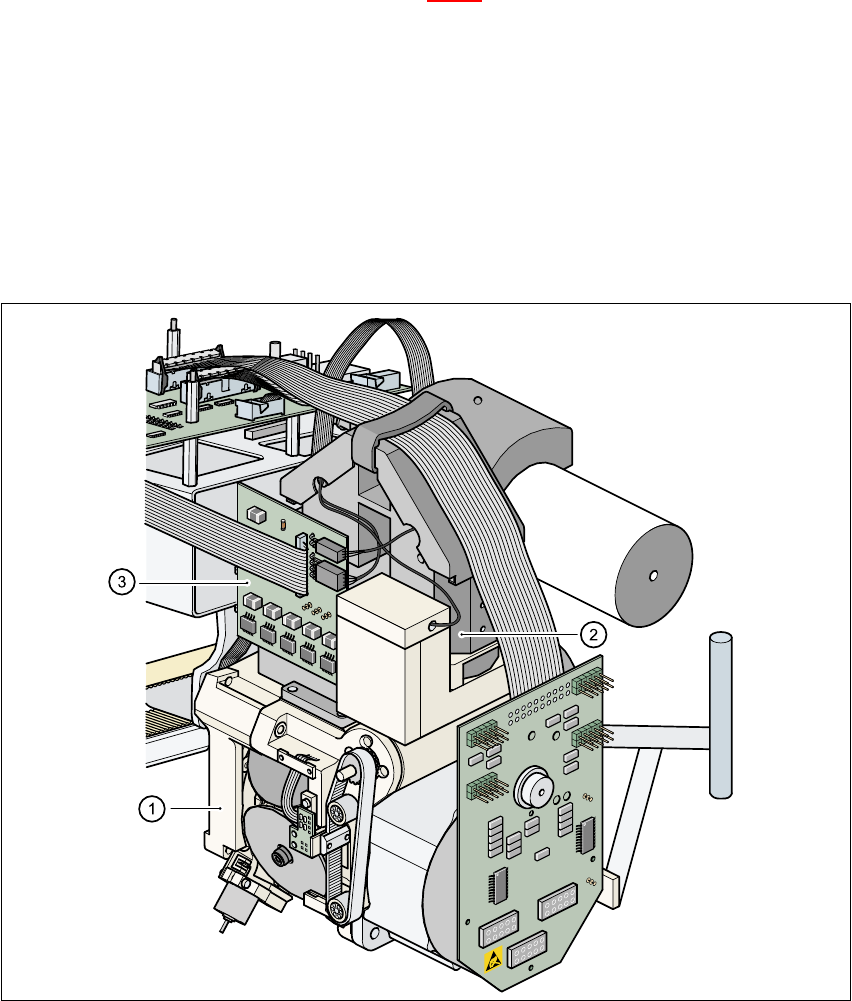
6.1.2 Component vision module on the 6-segment Collect&Place head
(standard vision module)
The component vison module (see item 2 in Fig. 6.1 - 6) essentially consists of the following mod-
ules: 6
– Optical lens
– CCD chip for creating an electronic image of the component
– CCD camera amplifier
– Three illumination levels – flat, average and steep – for optimum illumination of a wide
range of component shapes
–“Illumination control” board for setting the intensity of the individual illumination levels.
6
Fig. 6.1 - 3 Component camera system on the 6-segment Collect&Place head
(standard component vision module)
(1) 6-segment Collect&Place head
(2) 24 x 24 component camera
(3) Component illumination control board
User Manual SIPLACE F5/F5 HM 6 Vision functions
Software version SR.407.xx 01/2001 US Edition 6.1 The vision systems on the placement machine
225
The component camera system is fixed to the top of the Collect&Place head using four hexagon
socket-head screws. It is then held in place by two parallel pins. 6
The component camera system can be used to optically center and place components ranging
from 0402 up to and including 32mm x 32mm in size. The components therefore vary in size be-
tween 1.0mm x 0.5mm and 32mm x 32mm, and from 0.3mm to 8.5mm thick. The minimum lead
pitch can be as little as 0.5mm. 6
6 Vision functions User Manual SIPLACE F5/F5 HM
6.1 The vision systems on the placement machine Software version SR.407.xx 01/2001 US Edition
226
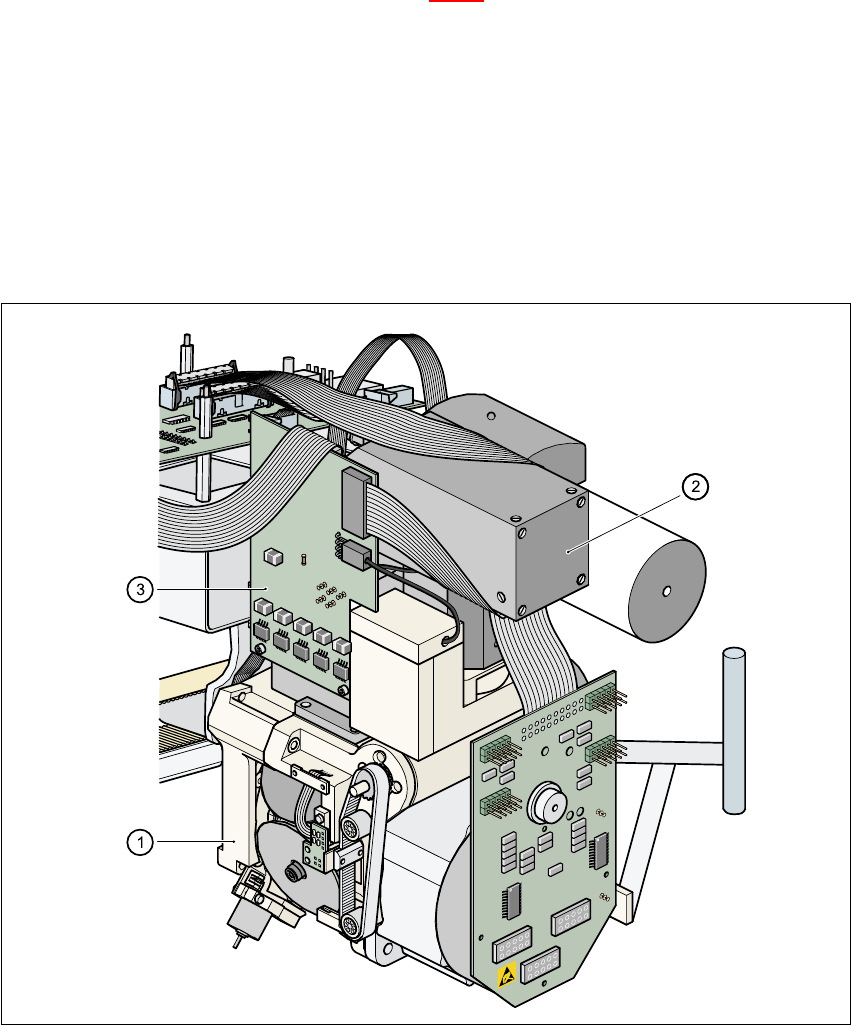
6.1.3 Component vision module on the 6-segment Collect&Place head
(DCA component vision module)
The component vision module (see item 2 in Fig. 6.1 - 4) essentially consists of the following mod-
ules: 6
– Optical lens
– CCD chip for creating an electronic image of the component
– CCD camera amplifier
– Four illumination levels – even, flat, average and steep – for optimum illumination of a wide
range of component shapes
–“Illumination control” board for setting the intensity of the individual illumination levels.
6
Fig. 6.1 - 4 Component camera system on the 6-segment Collect&Place head (DCA vision module)
(1) 6-segment Collect&Place head
(2) 15.7 x 15.7 component camera
(3) Component illumination control board