00192662-01.pdf - 第230页
6 Vision functions User Manua l SIPLACE F5/F5 HM 6.1 The vision s ystems on the placement mac hine Software version SR.407.xx 01/2001 US E dition 230 The PCB camera s ystem i s fixed to the Collec t&Place head on th …
User Manual SIPLACE F5/F5 HM 6 Vision functions
Software version SR.407.xx 01/2001 US Edition 6.1 The vision systems on the placement machine
229
6.1.5 PCB camera system
6
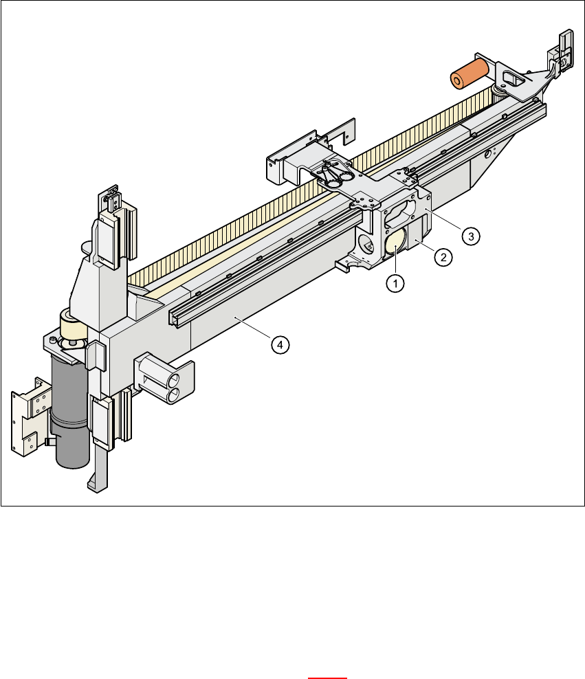
Fig. 6.1 - 6 PCB camera system, basic gantry – bottom view
(1) PCB camera – lens and illumination
(2) Camera amplifier
(3) Head mount
(4) Gantry
6
The PCB camera system (see item 1 and 2 in Fig. 6.1 - 6
) essentially consists of the following
components: 6
– Optical lens
– CCD chip
– CCD camera amplifier
– An illumination level for illuminating PCB fiducials and ink spots

6 Vision functions User Manual SIPLACE F5/F5 HM
6.1 The vision systems on the placement machine Software version SR.407.xx 01/2001 US Edition
230
The PCB camera system is fixed to the Collect&Place head on the underside of the gantry. As
standard, it can center PCBs from 50mm x 50mm up to 460mm x 460mm (2" x 2" to 18" x 18"),
with the thickness ranging from 0.5mm to 4.5mm. 6
6.1.6 Vision analysis unit
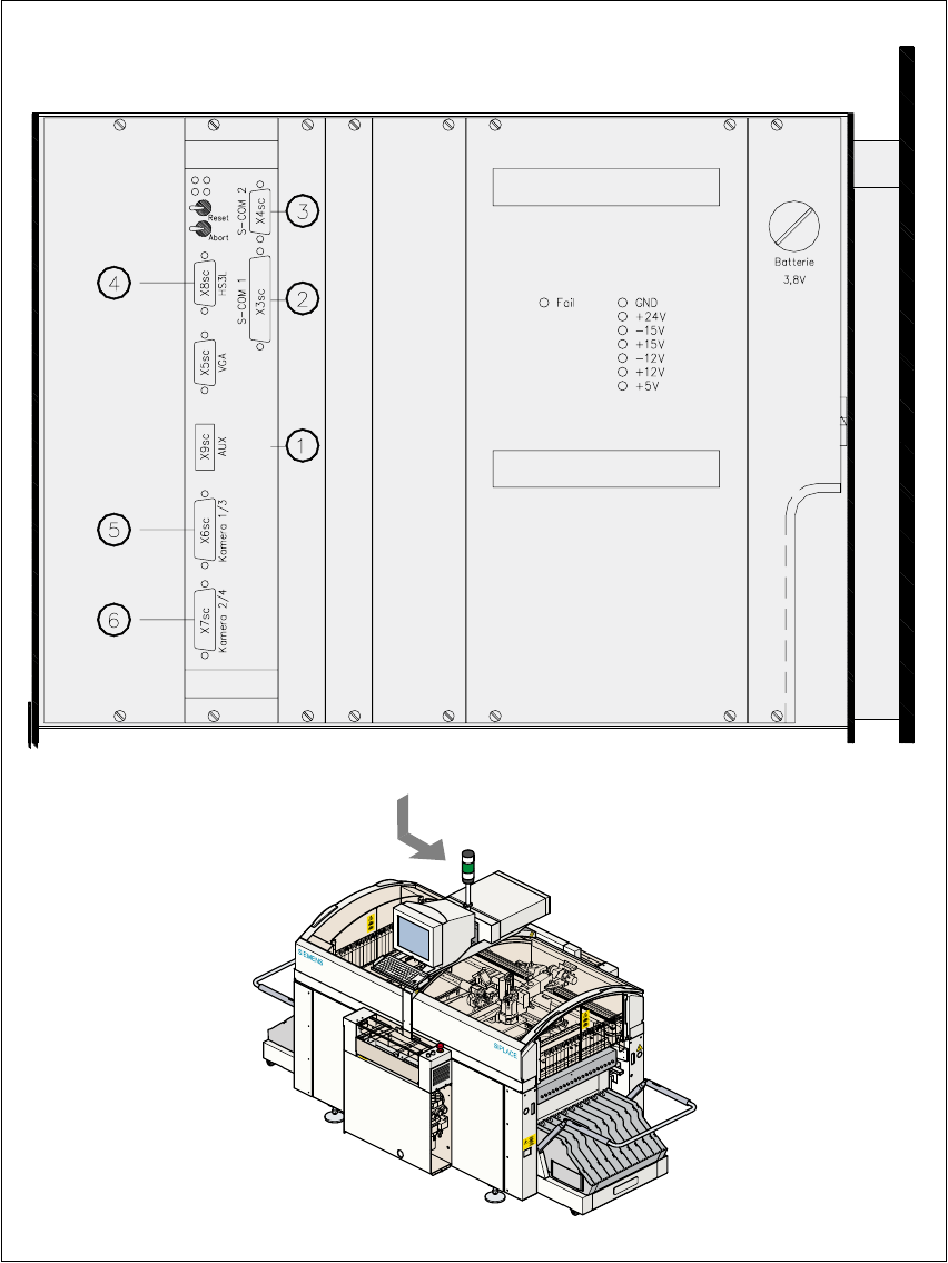
The vision analysis unit (see item 1 in Fig. 6.1 - 7) plugs into the machine’s control unit. It pro-
cesses and analyzes the electrical signals from the component and PCB camera systems. Cor-
rected values are calculated from any deviations from setpoint. These values are then used to
recalculate the placement positions and rotational angle for placement. 6
The vision analysis unit also performs a component identification process. If the synthetic model
and the package form measurement do not tally, for example, the component will not be placed. 6
The precise component pick-up position, which is particularly important for small components, is
also determined in the vision analysis unit. Fiducials on the feeders are used to determine the de-
viation in position of the individual feeders. 6
The electronic image signals from components, PCB fiducials, and feeder fiducials can be trans-
ferred from the vision analysis unit, via the video multiplexer, to the station monitor, where they are
used for measuring and testing purposes. 6
6
6
6
6
6
6
Key to Fig. 6.1 - 7
(1) MVS 340 vision analysis unit
(2) COM1 interface
(3) COM2 interface
(4) HS
3
L interface
(5) Camera connections:
1PCB camera
3 Component camera, 6-segment or 12-segment Collect&Place head
(6) Camera connections
2 Fine-pitch vision module
4 Flip-chip vision module
6
User Manual SIPLACE F5/F5 HM 6 Vision functions
Software version SR.407.xx 01/2001 US Edition 6.1 The vision systems on the placement machine
231
6
Fig. 6.1 - 7 Vision analysis unit
6