00192662-01.pdf - 第231页
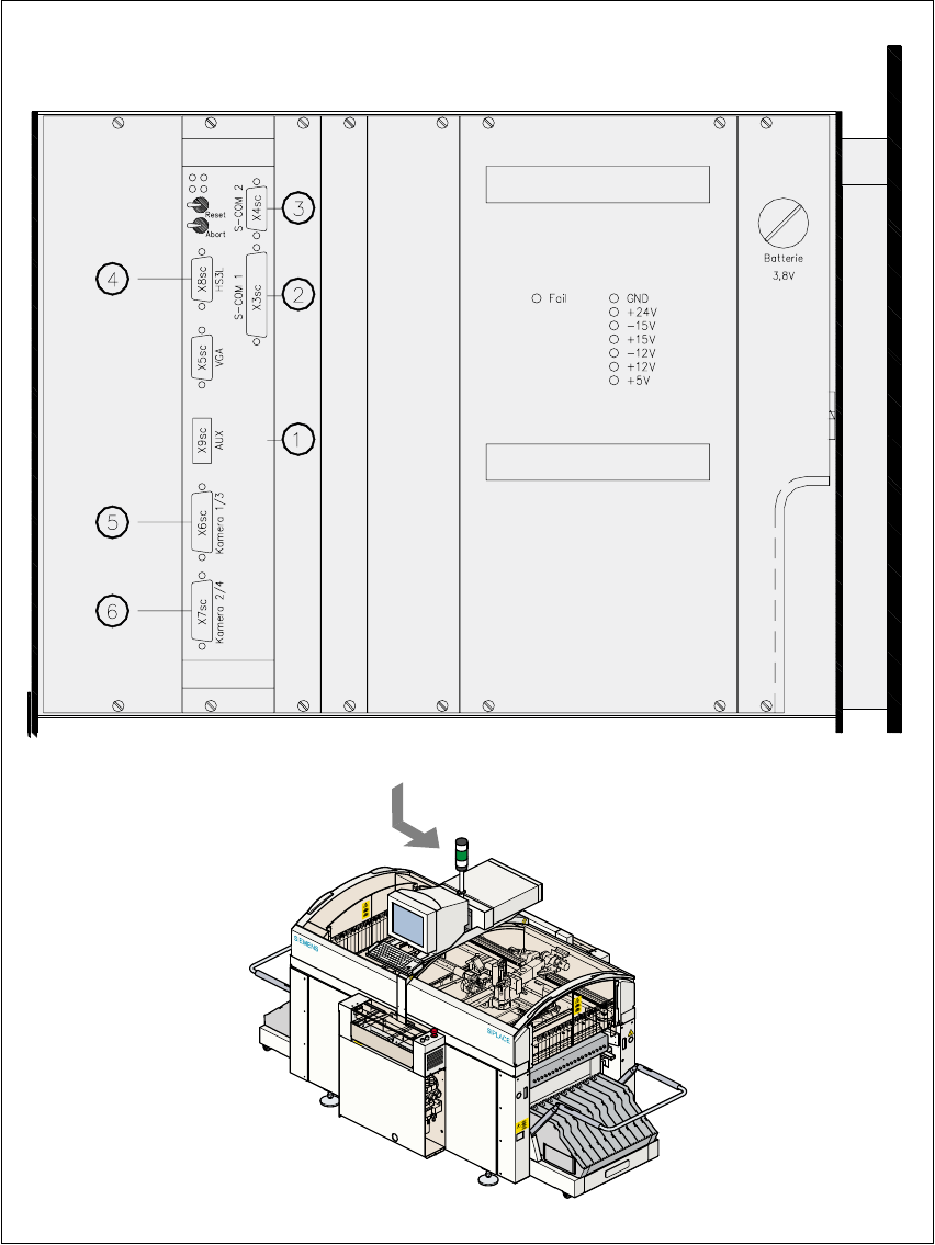
User Manual SIPLAC E F5/F5 HM 6 Vision functions Software version SR.407.xx 01/2001 US Edition 6.1 The vision systems on the placement machine 231 6 Fig. 6.1 - 7 V ision analysis unit 6

6 Vision functions User Manual SIPLACE F5/F5 HM
6.1 The vision systems on the placement machine Software version SR.407.xx 01/2001 US Edition
230
The PCB camera system is fixed to the Collect&Place head on the underside of the gantry. As
standard, it can center PCBs from 50mm x 50mm up to 460mm x 460mm (2" x 2" to 18" x 18"),
with the thickness ranging from 0.5mm to 4.5mm. 6
6.1.6 Vision analysis unit
The vision analysis unit (see item 1 in Fig. 6.1 - 7) plugs into the machine’s control unit. It pro-
cesses and analyzes the electrical signals from the component and PCB camera systems. Cor-
rected values are calculated from any deviations from setpoint. These values are then used to
recalculate the placement positions and rotational angle for placement. 6
The vision analysis unit also performs a component identification process. If the synthetic model
and the package form measurement do not tally, for example, the component will not be placed. 6
The precise component pick-up position, which is particularly important for small components, is
also determined in the vision analysis unit. Fiducials on the feeders are used to determine the de-
viation in position of the individual feeders. 6
The electronic image signals from components, PCB fiducials, and feeder fiducials can be trans-
ferred from the vision analysis unit, via the video multiplexer, to the station monitor, where they are
used for measuring and testing purposes. 6
6
6
6
6
6
6
Key to Fig. 6.1 - 7
(1) MVS 340 vision analysis unit
(2) COM1 interface
(3) COM2 interface
(4) HS
3
L interface
(5) Camera connections:
1PCB camera
3 Component camera, 6-segment or 12-segment Collect&Place head
(6) Camera connections
2 Fine-pitch vision module
4 Flip-chip vision module
6
User Manual SIPLACE F5/F5 HM 6 Vision functions
Software version SR.407.xx 01/2001 US Edition 6.1 The vision systems on the placement machine
231
6
Fig. 6.1 - 7 Vision analysis unit
6

6 Vision functions User Manual SIPLACE F5/F5 HM
6.2 PCB vision system Software version SR.407.xx 01/2001 US Edition
232
6.2 PCB vision system
The PCB vision system records the precise position of the PCB by measuring fiducials, and cal-
culates the offset in the X and Y directions, the angle of rotation relative to the PCB transport di-
rection and the shear acting on the PCB. Reject fiducials (ink spots) are also recorded and
analyzed by the PCB vision system. 6
6.2.1 System description
The PCB vision system for detecting the position of PCBs consists of the optical PCB position de-
tection system and the vision analysis unit 6
Optical PCB position detection system 6
Each gantry has a separate PCB position detection system (see Fig. 6.1 - 3 on page 224). 6
Vision analysis unit 6
On each machine, an analysis unit for PCB and component position recognition is housed in the
control unit (see Fig. 6.1 - 7
, page 231). 6
A CCD camera (SONY XC75) with integral mapping and illumination lens forms the optical PCB
position detection system. The field of view of the PCB module is 5.7 mm x 5.7 mm. The size and
position of the search field can be programmed as required within the fields of view. The mapping
lens is a special measuring lens which corrects most errors caused by the curvature of the PCB.
The illumination is switched on only while fiducials are being recorded. 6
The vision analysis unit (MVS) is a single-board system conforming to VME standards. The hard-
ware consists of 6
– the MVS motherboard with vision processor and interface connections
– and the MVS camera interface for up to four CCD cameras.
MVS motherboard with vision processor and interface connections 6
The two VME bus connections are located on the back of the VME module. 6
The front panel of the VME module contains connectors for 6
– the monitor (VGA mode, 15-pin SUBD connector)
– the high-speed interface (HS
3
L), 9-pin SUBD connector
– up to 4 camera inputs (2 x 15-pin SUBD connector)
– two serial interfaces (RS232 for COM1 with a 25-pin SUBD connector and COM2 with a
9-pin SUBD connector)