00192662-01.pdf - 第310页
6 Vision functions User Manua l SIPLACE F5/F5 HM 6.6 Test Co mponent Software version SR. 407.xx 01/2001 US E dition 310 6 Fig. 6.6 - 19 T est component menu, Test componen t video image Å With t he Return key you can c …
User Manual SIPLACE F5/F5 HM 6 Vision functions
Software version SR.407.xx 01/2001 US Edition 6.6 Test Component
309
6.6.4.3 Test Component Option
NOTE 6
This option can only be activated if you have already loaded a package form number and a com-
ponent has been picked up.
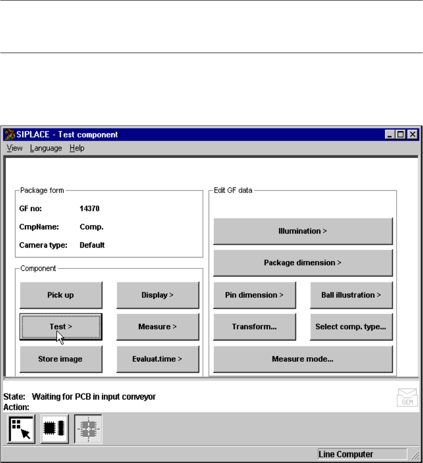
With this option you can check the centering procedure. Every time a measuring step has been
carried out the procedure is stopped for you to check the function individually. The measurement
results are displayed on the screen but not saved. 6
6
Fig. 6.6 - 18 Test component menu, Test component option
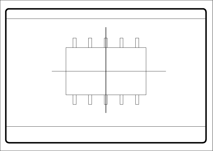
When this option is activated the following actions are started: 6
– The measurement procedure is activated.
– The video image appears on the screen.
– The header and footers are displayed.
6 Vision functions User Manual SIPLACE F5/F5 HM
6.6 Test Component Software version SR.407.xx 01/2001 US Edition
310
6
Fig. 6.6 - 19 Test component menu, Test component video image
Å With the Return key you can call all defined individual steps in the measurement procedure
one after the other. Each time you press the Return key another measurement step is carried
out and the results shown on the screen.
Å Use Esc to quit the option. The video image closes and the Test component menu reappears.
GF no. = 5Test component
RET: Test component
User Manual SIPLACE F5/F5 HM 6 Vision functions
Software version SR.407.xx 01/2001 US Edition 6.6 Test Component
311
6.6.4.4 Measure Component Option
NOTE 6
This option can only be activated if you have already loaded a package form number and a com-
ponent has been picked up.
6
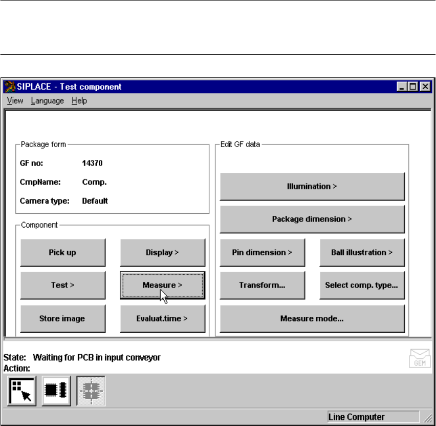
Fig. 6.6 - 20 Test component menu, Measure component option
When this option is activated the following actions are started: 6
– The video image appears on the screen.
– The measurement command is given, using the predefined parameters.
– The MVS performs each component-specific measurement step in turn.
– The measurement values are displayed in the video image.