00192662-01.pdf - 第340页
6 Vision functions User Manua l SIPLACE F5/F5 HM 6.6 Test Co mponent Software version SR. 407.xx 01/2001 US E dition 340 Method for calculat ing the rotation 6 Here you must spe cify the number of rotation wind ows in or…
User Manual SIPLACE F5/F5 HM 6 Vision functions
Software version SR.407.xx 01/2001 US Edition 6.6 Test Component
339
6.6.4.16 ‘Size’ measuring mode
Click on the ‘Setting’ field for the ‘Size’ measuring mode to overlay the Size measuring mode
menu on the screen. 6
6
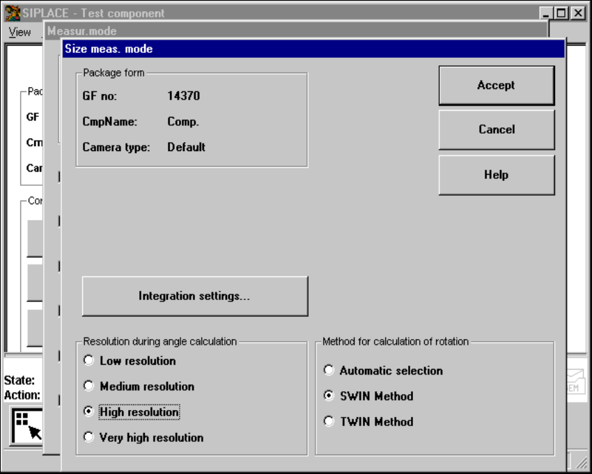
Fig. 6.6 - 35 Measuring mode option, Size measuring mode menu
This menu is used to 6
– vary the resolution the angle calculation.
– specify the method for the rotation calculation and
– vary the integration settings.
Resolution for the angle calculation 6
In this measuring mode, if the component rotation has been calculated incorrectly on account of
ambiguity, you can increase the angular resolution in order to determine the angle of rotation. The
following increments may be used in relation to the resolution in order to determine the angle of
the components: 6
– Simple components:Low resolution:
– Complex components:High resolution
6 Vision functions User Manual SIPLACE F5/F5 HM
6.6 Test Component Software version SR.407.xx 01/2001 US Edition
340
Method for calculating the rotation 6
Here you must specify the number of rotation windows in order to determine the angle: 6
– Automatic selection
The system selects the number of windows.
– SWIN method (Single Window)
Selects a single window. This method is suitable for small and complex components or com-
ponents with fluctuating dimensions.
– TWIN method (Two Windows)
Two windows are selected. This method is particularly suitable for rapid analysis, for PLCCs,
for example. However, this requires the structures to be investigated to lie in the center of the
window. If this is not the case, select just one window (SWIN method).
Integration settings 6
If you click on the 'Integration settings' field, the Integration settings of Size measuring mode
menu will appear on screen. 6
6
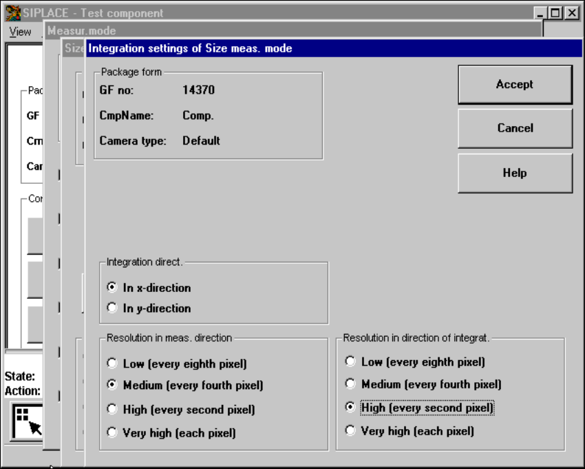
Fig. 6.6 - 36 Measuring mode option, Integration settings of Size measuring mode menu

User Manual SIPLACE F5/F5 HM 6 Vision functions
Software version SR.407.xx 01/2001 US Edition 6.6 Test Component
341
This menu is used to select the 6
– integration direction,
– the resolution in the measuring direction and
– the resolution in the integration direction.
Integration direction 6
In order to determine the angle, select the integration direction towards either the X or Y axis of
the component. We recommend that you select the longer edge. 6
Resolution in the measuring direction 6
Select this resolution in order to optimize the measuring times at the Collect&Place head. 6
Resolution in the integration direction 6
Select this resolution in order to optimize the measuring times at the Collect&Place head. 6
Resolution
in the measuring direction
Resolution
in the integration direction
Small components very high very high
Large components with an-
other measuring step to follow high medium
Tab. 6.6.1