00192662-01.pdf - 第347页
User Manual SIPLAC E F5/F5 HM 6 Vision functions Software version SR.407.xx 01/2001 US Edition 6.6 Test Component 347 Windows 6 – Separat ely for each lead Here you def ine the win dow in the prim ary dir ection (dark bl…
6 Vision functions User Manual SIPLACE F5/F5 HM
6.6 Test Component Software version SR.407.xx 01/2001 US Edition
346
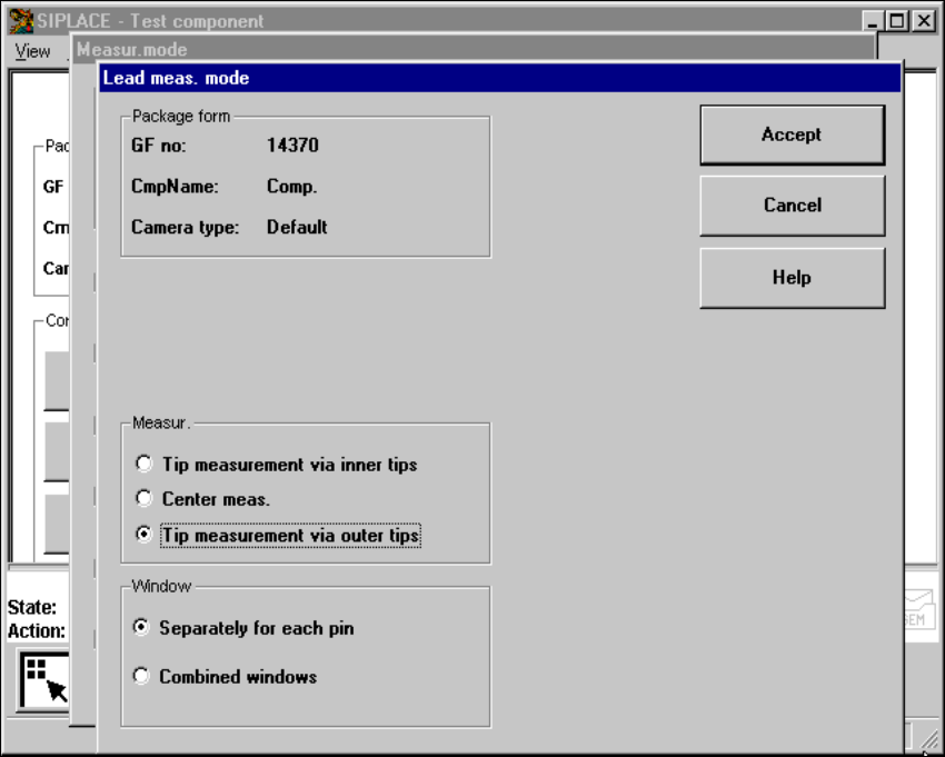
6.6.4.19 ‘Lead’ measuring mode
Click on the ‘Setting’ field in the ‘Lead’ measuring mode to call up the Lead measuring mode
menu. 6
6
Fig. 6.6 - 40 Measuring mode option, Lead measuring mode menu
This menu is used to 6
– specify the lead measuring method.
– to select the windows separately for each lead or a combined window for every lead to be mea-
sured.
Measurement 6
If the inner lead tips are mapped better than the outer tips, for example if a shiny lead is bent up-
wards slightly, you can select one of the following options: 6
– measuring the tips via the inner tips of the leads, for bases, for example
– center of the lead, center measurement, for PLCC, SOJ, for example
– measuring the tips via the outer tips of the leads, for QFP, SOT, SO, for example
User Manual SIPLACE F5/F5 HM 6 Vision functions
Software version SR.407.xx 01/2001 US Edition 6.6 Test Component
347
Windows 6
– Separately for each lead
Here you define the window in the primary direction (dark blue) and secondary direction (light
blue) for measuring each standard lead for irregular components and special components.
– Combined window
Used to define a common window for all the leads. This applies to four-sided, symmetrical
components only.
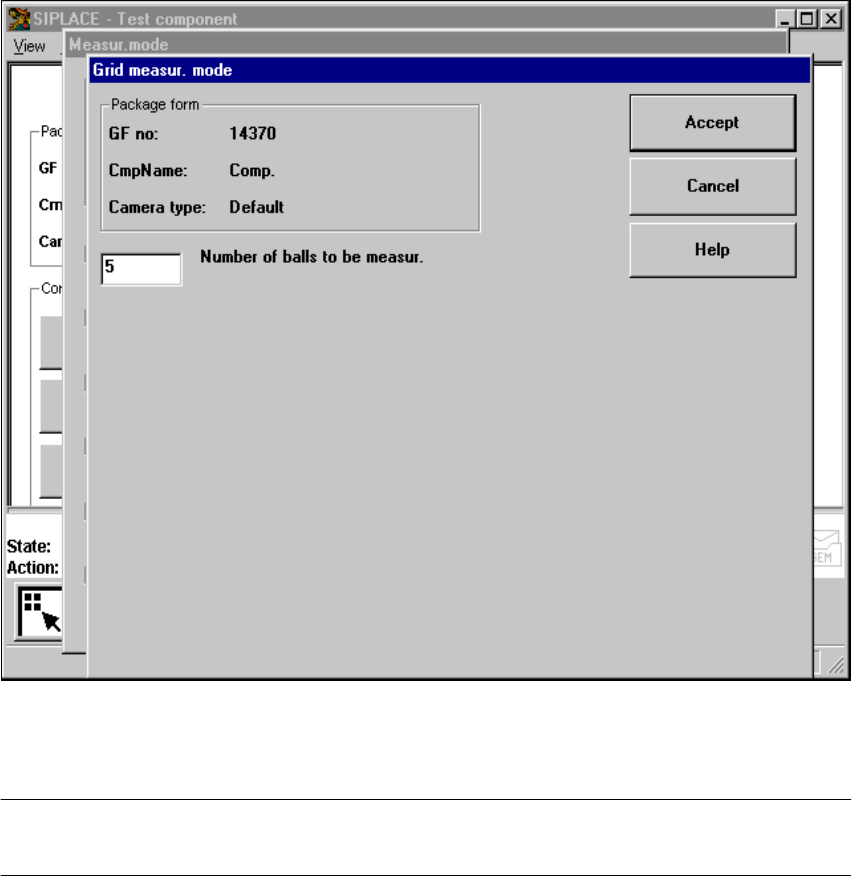
6.6.4.20 ‘Grid’ measuring mode
Click on the ‘Setting’ field in the ‘Grid’ measuring mode to call up the Grid measuring mode
menu. 6
Fig. 6.6 - 41 Measuring mode option, Grid measuring mode menu
In this menu, enter the number of balls to be measured at each corner: ’3’ for single measurement
and 5 for multiple measurement 6
PLEASE NOTE: Measurement mode Grid can be speeded up, if measurement mode Size is car-
ried out beforehand. 6
6 Vision functions User Manual SIPLACE F5/F5 HM
6.6 Test Component Software version SR.407.xx 01/2001 US Edition
348
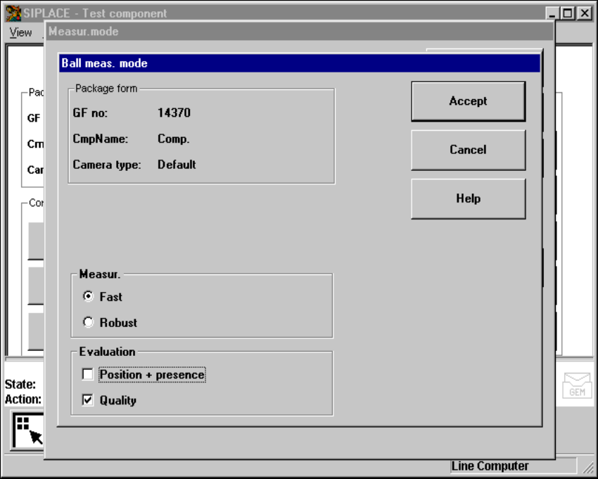
6.6.4.21 ’Ball’ measuring mode
Click on the ’Settings’ button in ’Ball’ measuring mode to call up the ’Ball measuring mode’ menu.6
6
Fig. 6.6 - 42 ’Measuring mode’ option, ’Ball meas. mode’ menu
This menu can be used to 6
– select the measuring methods listed under ’Measurement’ and
– evaluate the position and presence of balls and carry out a quality analysis.