00192662-01.pdf - 第371页
User Manual SIPLAC E F5/F5 HM 6 Vision functions Software version SR.407.xx 01/2001 US Edition 6.7 Guidelines for Describing Pack age Forms 371 6 Fig. 6.7 - 10 Illumination parameters for other components on the f ine-pi…
6 Vision functions User Manual SIPLACE F5/F5 HM
6.7 Guidelines for Describing Package Forms Software version SR.407.xx 01/2001 US Edition
370
6
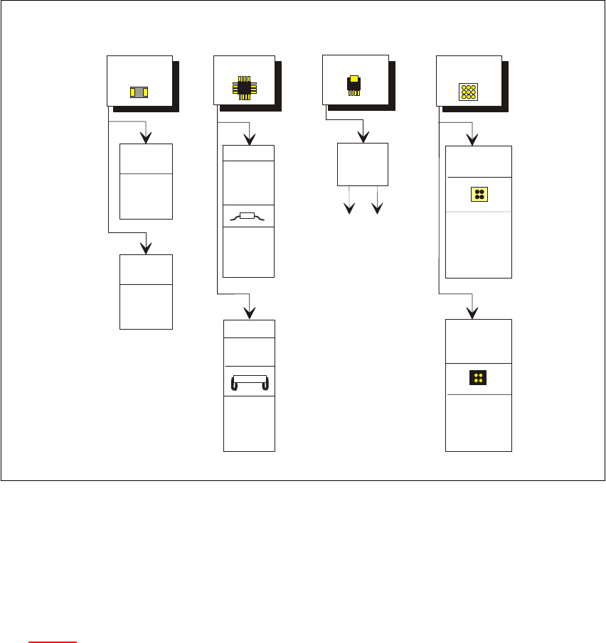
Fig. 6.7 - 9 Illumination parameters for standard components on the fine-pitch vision module
6
6
6.7.7.4 Settings for Illuminating Other Components
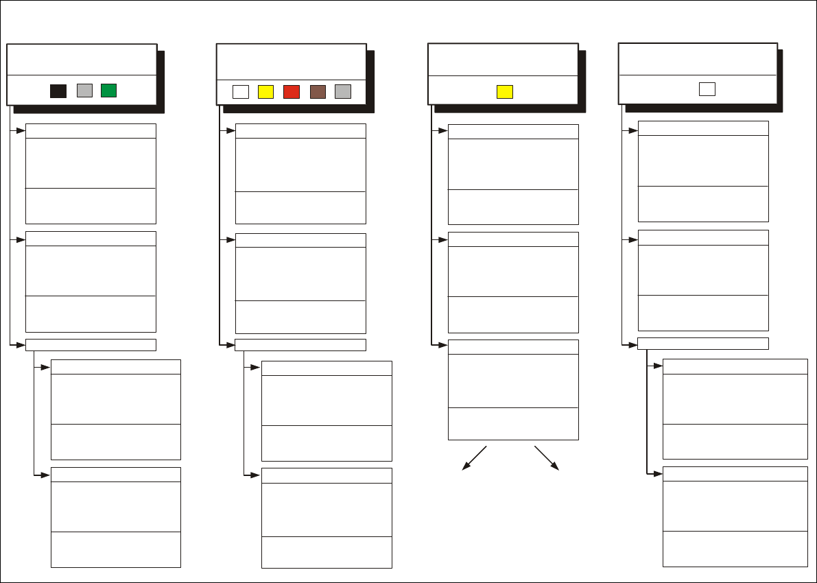
Fig. 6.7 - 10 presents a list of the illumination settings for other components. 6
Diagram for adjusting the illumination of standard components
IC
Power IC
BGA
Tantalum
capacitor
BGA
General
flat: 120
middle: 60
steep: 10
Reflective
body
Gullwing
SO, SOT,
TSOP
QFP,
flat: 90
middle: 40
steep: 10
flat: 255
middle: 90
steep: 0
flat: 120
middle: 50
steep: 10
J-Lead
PLCC
flat: 200
middle: 30
steep: 5
Ceramic
BGA
flat: 0
middle: 0-10
steep:80-100
flat: 255
middle: 30
steep: 0
Illumination
level
Brightness
User Manual SIPLACE F5/F5 HM 6 Vision functions
Software version SR.407.xx 01/2001 US Edition 6.7 Guidelines for Describing Package Forms
371
6
Fig. 6.7 - 10 Illumination parameters for other components on the fine-pitch vision module
Adjusting the illumination of other compon
ents
Illumination level Brightness
Glänzende Beinchen
flat:
middle:
steep:
160
60
0
flat:
middle:
steep:
0
0
25
1. Illuminate body and leads equally.
Measure outline.
2. Trick: Use flat and middle levels to
bring leads image to saturation.
flat:
middle:
steep:
160
60
0
flat:
middle:
steep:
150-255
255
60-120
90
0
0
for variant 2:
flat:
flat:
middle:
middle:
steep:
steep:
120
120
40
40
0-10
0-10
flat:
middle:
steep:
100
30
40
flat:
middle:
steep:
100
30
40
flat:
middle:
steep:
90
40
10
flat:
middle:
steep:
200
30
5
flat:
flat:
middle:
middle:
steep:
steep:
0
0
0
0
20-40
20-40
flat:
middle:
steep:
90
40
10
flat:
middle:
steep:
200
30
5
flat:
middle:
steep:
90
90
5-10
flat:
middle:
steep:
120-140
40-60
0-10
flat:
middle:
steep:
Light and dull body
( white, yellow, red, brown,
grey,
metallic dull )
Ceramic body
Dark and dull body
( black, blue, green )
Reflective body
(independently of color and ma
terial)
Gullwing leads ( SO, QFP)
Clear separation
between lea
ds
and body.
J-L
ead ( PLCC ), convex-type leads
Clear separation
between leads
and body.
Shiny leads
Clear separation
between leads
and body.
Other lead shapes
Dull leads
Clear separation
between leads
and body.
Visual separation between leads
and body is not possible. Measure
outline or lead tips. Leads are
outside the body.
Gullwing leads ( SO, QFP )
Visual separation between leads
and body is not possible.
Illuminate body and leads equally.
Measure outline.
J-Lead ( PLCC ), convex-type leads
Other lead shapes
Visual separation between leads
Visual separation between leads
and body is not generally possible.
and body is not generally possible.
Leads:
Leads:
Outline:
Outline:
Measuring method:
Measuring method:
Shiny leads
Dull leads
Shiny leads
Clear separation
between leads
and body.
Dull leads
Visual separation between leads
and body is not possible.
Illuminate body and leads equally.
Measure outline.
Measure outline.
Convex-type leads
Visual separation between leads
and body is not generally possible.
Illuminate body and leads equally.
Gullwing leads ( SO, QFP )
Clear separation
between leads
and body.
J-Lead ( PLCC ), convex-type leads
Clear separation
between leads
and body.
Other lead shapes
Dull leads
Clear separation
between leads
and body.

6 Vision functions User Manual SIPLACE F5/F5 HM
6.7 Guidelines for Describing Package Forms Software version SR.407.xx 01/2001 US Edition
372
6.7.7.5 Testing Illumination Settings
You can set the illumination parameters by calling the ’Illumination’ option (see Section 6.6.4.8 on
page 325
). Using the ’Measure Component Option’ on page 311 you can then measure the com-
ponent and check your settings with the aid of the measurement results. 6
Proceed as follows to test your illumination setting: 6
Å Using the illumination values suggested in Figures 6.7 - 9 or 6.7 - 10 carry out measurement.
Measurement should run through successfully.
Å For each level reduce the set brightness level by 50 %.
Measurement should run through successfully.
Å For each level raise the set brightness level by 50 %.
Measurement should run through successfully.
If you are not successful with the above procedure, proceed as follows: 6
Å Starting with the suggested illumination value, increase the brightness of each individual illu-
mination level for as long as measurement is still successful.
Å Find this upper limit value for each individual illumination level in turn.
Å Starting with the suggested illumination value, decrease the brightness of each individual illu-
mination level for as long as measurement is still successful. Find this lower limit value for each
individual illumination level in turn.
Å Determine the average value of the upper and lower limit values. This will be the optimum illu-
mination value.
Example of an illumination test: 6
– Settings from the diagram:
flat: 170
middle: 60
steep: 5
– Measure the component. Measurement is successful.
– Reduce setting values by 50%.
flat: 85
middle: 30
steep: 2
– Increase setting values by 50%.
flat: 255
middle: 90
steep: 8