00192662-01.pdf - 第374页
6 Vision functions User Manua l SIPLACE F5/F5 HM 6.7 Guidelines for Describing Pa ckage Forms Software version S R.407.xx 01/2001 US Edition 374 Flat illumi nation level 6 The flat ill umina tion lev el is us ed for il l…
User Manual SIPLACE F5/F5 HM 6 Vision functions
Software version SR.407.xx 01/2001 US Edition 6.7 Guidelines for Describing Package Forms
373
– Measure the component. Measurement is successful.
– Reset the settings to the suggested values:
flat: 170
middle: 60
steep: 5
© optimum setting
6
6.7.7.6 General Information on Setting Illumination Values
– As a rule it is better to overilluminate the component than to underilluminate it. A saturated im-
age is preferable to a low-contrast image.
– Optimum illumination is attained when only the leads are imaged and the component body is
not shown.
– If you cannot clearly separate the image of the component body from the leads, we recom-
mend to illuminate body and leads equally and then to measure the outline.
6.7.8 Setting the Component Illumination on the 6-Segment Revolver Head
Camera (Standard Vision Module)
6.7.8.1 General Information on Illumination Methods
The idea of illumination setting is to obtain an image of the leads of a component which is as high-
contrast as possible. At the same time it is also important to suppress representation of the body
of the component. 6
These instructions are intended to help you find the best possible illumination parameters. This,
however, does not imply that you rigidly comply with the values specified in these instructions. The
way you should proceed is first to follow these instructions and then to adjust the parameters your-
self where necessary. It may well be that you come across a component where the leads are better
illuminated using values different than the ones suggested in these instructions. 6
The illumination system consists of two different illumination levels. The intensities can be pro-
grammed individually. By using the individual illumination levels one at a time or in combination,
you can adapt the illumination to suit a wide range of components. 6
6 Vision functions User Manual SIPLACE F5/F5 HM
6.7 Guidelines for Describing Package Forms Software version SR.407.xx 01/2001 US Edition
374
Flat illumination level 6
The flat illumination level is used for illuminating BGAs, µBGAs, flip-chips, J-lead components
(PLCC), Melfs and components with convex-type leads. It tends to emphasize body and lead
edges. It is, however, less suitable for displaying bright component bodies and ceramic compo-
nents. 6
Steep illumination level 6
The main application for the steep illumination level is for reflective leads, ceramic components
and bright component bodies. It is less suitable for reflective component bodies, flip-chips or
µBGAs. 6
NOTE 6
Most components will require a combination of these illumination levels to achieve optimum illu-
mination. Using one illumination level will only be successful in exceptional cases.
6.7.8.2 Pseudo Color Representation
The pseudo color representation provides a powerful and objective assessment of the illumina-
tion, by representing a brightness value in a color. 6
A contrast of at least 4 color scales between the lead and body is required for a measurement. In
the ‘Illumination’ menu of the package form manipulator, components are displayed in the pseudo
color representation on the station computer monitor. 6
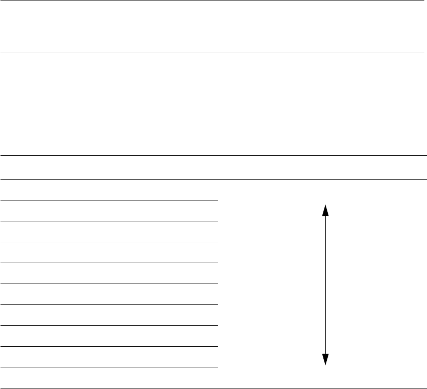
Color scale Brightness
white light
yellow
orange
red
brown
green
light blue
blue
violet
black dark

User Manual SIPLACE F5/F5 HM 6 Vision functions
Software version SR.407.xx 01/2001 US Edition 6.7 Guidelines for Describing Package Forms
375
6.7.8.3 Settings for Illuminating Standard Components
The standard range of components includes chips (0603 to 2220), tantalum capacitors, Melf com-
ponents, PLCCs, QFPs, SOs, SOJs, TSOPs, ICs, power components, flip-chips, µBGAs and
BGAs. 6
For the components which are listed below the GF interpreter in the station computer uses the
default illumination parameters listed in Fig. 6.7 - 11
: 6
– Chips (0603 to 2220)
– Tantalum capacitors (component bodies, non-reflective)
– Melf
– PLCC, QFP, SO, SOJ, TSOP, ICs, power ICs
– Flip-chips, µBGAs, BGAs
6
The odd-shaped components include 6
– power transistors
– plug connectors
– PLCC sockets
– quartz crystals
It is not generally necessary to modify the illumination parameters for different components. 6