00192662-01.pdf - 第378页
6 Vision functions User Manua l SIPLACE F5/F5 HM 6.7 Guidelines for Describing Pa ckage Forms Software version S R.407.xx 01/2001 US Edition 378 NOTE 6 With resp ect to 0603 co mponents, av oid the no zzle bei ng disp la…

User Manual SIPLACE F5/F5 HM 6 Vision functions
Software version SR.407.xx 01/2001 US Edition 6.7 Guidelines for Describing Package Forms
377
6.7.8.4 Testing Illumination Settings
You can set the illumination parameters by calling the ’Illumination’ option (see Section 6.6.4.8 on
page 325
). Using the ’Measure Component Option’ on page 311 you can then measure the com-
ponent and check your settings with the aid of the measurement results. 6
Proceed as follows to test your illumination setting: 6
Å Using the illumination values suggested in Figure 6.7 - 11 carry out measurement. Measure-
ment should run through successfully.
Å For each level reduce the set brightness level by 50 %.
Measurement should run through successfully.
Å For each level raise the set brightness level by 50 %.
Measurement should run through successfully.
If you are not successful with the above procedure, proceed as follows: 6
Å Starting with the suggested illumination value, increase the brightness of each individual illu-
mination level for as long as measurement is still successful.
Å Find this upper limit value for each individual illumination level in turn.
Å Starting with the suggested illumination value, decrease the brightness of each individual illu-
mination level for as long as measurement is still successful. Find this lower limit value for each
individual illumination level in turn.
Å Determine the average value of the upper and lower limit values. This will be the optimum illu-
mination value.
Example of an illumination test: 6
– Settings from the diagram:
flat: 150
steep: 180
– Measure the component. Measurement is successful.
– Reduce setting values by 50%.
flat: 75
steep: 90
– Increase setting values by 50%.
flat: 225
steep: 255
– Measure the component. Measurement is successful.
– Reset the settings to the suggested values:
flat: 150
steep: 180
© optimum setting

6 Vision functions User Manual SIPLACE F5/F5 HM
6.7 Guidelines for Describing Package Forms Software version SR.407.xx 01/2001 US Edition
378
NOTE 6
With respect to 0603 components, avoid the nozzle being displayed during imaging. If this seems
likely, remove the component from the nozzle and use the ’Illumination Option
’ (see page 325 to
see whether the nozzle did appear in the image.
6.7.8.5 General Information on Setting Illumination Values
– As a rule it is better to overilluminate the component than to underilluminate it. A saturated im-
age is preferable to a low-contrast image.
– Optimum illumination is attained when only the leads are imaged and the component body is
not shown.
– If you cannot clearly separate the image of the component body from the leads, we recom-
mend to illuminate body and leads equally and then to measure the outline.
6.7.9 Setting the Component Illumination on the 6-Segment Revolver Head
Camera (Vision Module for Flip-Chips, Bare Dies, etc, DCA Option)
6.7.9.1 General Information on Illumination Methods
The idea of illumination setting is to obtain an image of the leads of a component which is as high-
contrast as possible. At the same time it is also important to suppress representation of the body
of the component. 6
These instructions are intended to help you find the best possible illumination parameters. This,
however, does not imply that you rigidly comply with the values specified in these instructions. The
way you should proceed is first to follow these instructions and then to adjust the parameters your-
self where necessary. It may well be that you come across a component where the leads are better
illuminated using values different than the ones suggested in these instructions. 6
The illumination system consists of four different illumination levels, the intensity of which can be
programmed separately. By using the individual illumination levels one at a time or in combination,
you can adapt the illumination to suit a wide range of components. 6
X-plane illumination level 6
The even illumination level is particularly suitable for flip-chips, µBGAs, and MELF components,
since it highlights the balls extremely clearly.
Flat illumination level 6
The flat illumination level is used for illuminating BGAs, µBGAs, flip-chips, J-lead components
(PLCC), Melfs and components with convex-type leads. It tends to emphasize body and lead
User Manual SIPLACE F5/F5 HM 6 Vision functions
Software version SR.407.xx 01/2001 US Edition 6.7 Guidelines for Describing Package Forms
379
edges. It is, however, less suitable for displaying bright component bodies and ceramic compo-
nents. 6
Middle illumination level 6
The middle illumination level can be used universally with a wide range of components. With bright
component bodies, ceramic components, µBGAs and flip-chips it should, however, only be used
at lower intensity levels. 6
Steep illumination level 6
The main application for the steep illumination level is for reflective leads, ceramic components
and bright component bodies. It is less suitable for bare dies, flip-chips or µBGAs. 6
NOTE 6
Most components will require a combination of these illumination levels to achieve optimum illu-
mination. Using one illumination level will only be successful in exceptional cases.
6.7.9.2 Pseudo color representation
The pseudo color representation provides a powerful and objective assessment of the illumina-
tion, by representing a brightness value in a color. 6
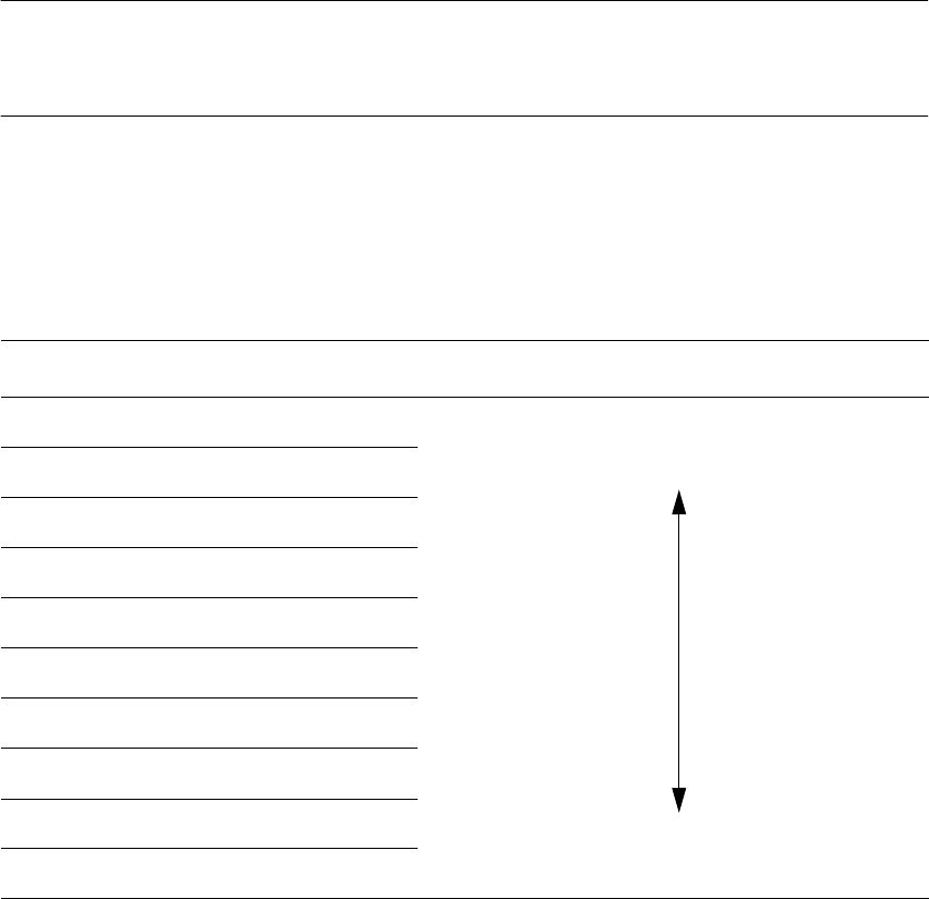
Color scale Brightness
white light
yellow
orange
red
brown
green
light blue
blue
violet
black dark