00192662-01.pdf - 第39页
User Manual SIPLACE F5/F 5 HM 1 Introduction and technical data Software version SR.407.xx 01/2001 US Edition 1.6 The line concept 39 1.6 The line concept 1.6. 1 Ove rview The mach ine can be linked to input/ou tput stat…

1 Introduction and technical data User Manual SIPLACE F5/F5 HM
1.5 Machine description Software version SR.407.xx 01/2001 US Edition
38
1.5.5 Technical data – overview of the SIPLACE F
5
HM
* The SIPLACE F5 HM can be equipped to place 0201 components.
(Please contact the factory for details).
** Only applies to the DCA package
*** Only applies to the DCA package and flip-chip component vision module for the Pick&Place head
1
Procedure Pick&place / collect&place
Component range
Standard vision module
DCA vision module
from 0603 to 55mm x 55mm
from 0.5mm x 0.25mm (0201*) to 55mm x 55mm
Max. placement rate
6-segment Collect&Place head
12-segment Collect&Place head
Pick&Place head
8,000 components/hour
11,500 components/hour
1,800 components/hour
6-segment Collect&Place head
Angular accuracy
Placement accuracy
± 0.225°/ 3 σ, ± 0.30°/ 4 σ, ± 0.45°/ 6 σ
± 52.5µm / 3 σ, 70µm / 4 σ, 105µm / 6 σ
± 45µm / 3 σ, 60µm / 4 σ, 90µm / 6 σ) **
12-segment Collect&Place head
Collect&Place Angular accuracy
Placement accuracy
± 0.525°/ 3 σ, ± 0.70°/ 4 σ, ± 1.05°/ 6 σ
± 67.5µm / 3 σ, 90µm / 4 σ, 135µm / 6 σ
Pick&Place head
Angular accuracy
Placement accuracy
± 0.052°/ 3 σ, ± 0.07°/ 4 σ, ± 0.105°/ 6 σ
± 37.5µm / 3 σ, 50µm / 4 σ, 75µm / 6 σ
(± 30µm / 3 σ, 40µm / 4 σ, 60µm / 6 σ) ***
PCB format 50mm x 50mm to 460mm x 460mm
(optionally 460mm x 508mm,18" x 20")
Feeder capacity 40 locations for feeders
Component supply
Types of feeder
Changeover table, wafflepack changer, manual WPC
trays
Component tapes, stick magazines, bulk cases
Operating system Microsoft Windows NT / RMOS
Connection In-line or stand alone
Space required 4 m² / module

User Manual SIPLACE F5/F5 HM 1 Introduction and technical data
Software version SR.407.xx 01/2001 US Edition 1.6 The line concept
39
1.6 The line concept
1.6.1 Overview
The machine can be linked to input/output stations, screen printing systems, soldering ovens and
other machines from the SIPLACE range (HS-50, S-20, F
4
, F
5
/F
5
HM, and the SIPLACE G adhe-
sive application station). All SIPLACE modules are supplied with the necessary data by the UNIX
line computer. The placement machine can also be linked to a higher level data processing system
through the use of suitable interfaces. 1
1.6.2 Technical data – line concept
1
*) SIPLACE HS-50, SIPLACE 80 S-20, SIPLACE 80 S-23 HM or SIPLACE 80 F
4
with 12-segment
Collect&Place head 1
**) SIPLACE 80 F
4
/F
5
/F
5
HM 1
1
1
System SIPLACE placement lines
Modules SIPLACE HS-50 / SIPLACE 80 S-20 / SIPLACE S-23 HM
SIPLACE 80 F
4
/ SIPLACE F
5
/ SIPLACE F
5
HM
Peripherals Input/output stations
Screen printers
Soldering ovens
Inspection stations, etc.
Component range From 0402 * to 55 mm x 55 mm **
PCB conveyor Automatic width adjustment
PCB format 50 mm x 50 mm to 460 mm x 460 mm
Placement rate Depends on how the modules are connected to one another
Space required 4 m² / SIPLACE 80 module
7.5 m² / SIPLACE HS-50 module
1 Introduction and technical data User Manual SIPLACE F5/F5 HM
1.7 Electrical and pneumatic connection points Software version SR.407.xx 01/2001 US Edition
40
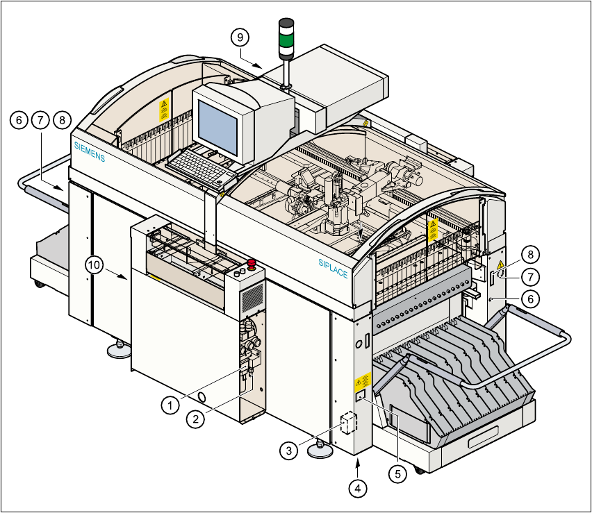
1.7 Electrical and pneumatic connection points
1
Fig. 1.7 - 1 Electrical and pneumatic connection points on the machine
(1) Compressed air unit
(2) Connection for compressed air line
(3) Main power filter Z1
(4) Hole for power cable
(5) Service socket
(6) Compressed air connection for changeover table
(7) Power supply connection for changeover table
(8) Communications connection for changeover table
(9) LAN supply in control unit
(10) Main switch