00192662-01.pdf - 第475页
User Manual SIPLAC E F5/F5 HM 10 Component han dling Software version SR.407.xx 01/2001 US Edition 10.9 Insertion of Components With a Height Clearance of up to 21 mm 475 10.9 Insertion of Component s With a Height Cl ea…
10 Component handling User Manual SIPLACE F5/F5 HM
10.8 Support for Flatpack Magazine (Manual Tray Rest) Software version SR.407.xx 01/2001 US Edition
474
10.8.3 Changing the Retainer
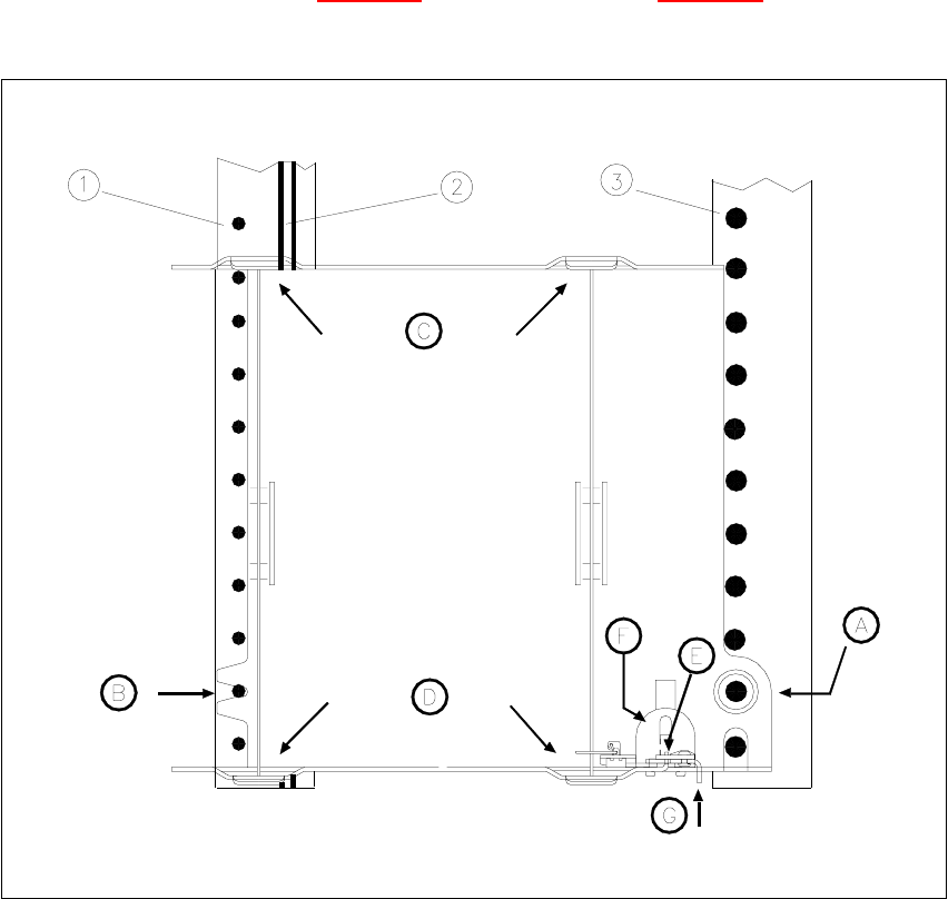
Å Hold the retainer firmly (G in Fig. 10.7.4). Press the clamp (F in Fig. 10.7.4) downwards and
remove the retainer by pressing it out sideways.
Fig. 10.8 - 1 Installation/Removal
(1) Centering pins
(2) Magnetic rail
(3) Spherical caps
10.8.4 Data Input
Define the flatpack magazines as described in the SIPLACE UNIX line computer UNIX user’s 10
manual.
10
10
User Manual SIPLACE F5/F5 HM 10 Component handling
Software version SR.407.xx 01/2001 US Edition 10.9 Insertion of Components With a Height Clearance of up to 21 mm
475
10.9 Insertion of Components With a Height Clearance
of up to 21 mm
10.9.1 Defining the Height Clearance
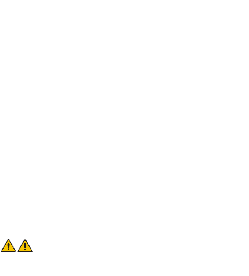
Height clearance means the distance between the upper transport edge of the PCB and the upper
edge of the component, i.e. 10
10
10
In other words, the height clearance specifies the height that a placement head needs in order to
avoid the risk of a head crash when holding a component. 10
10.9.2 How to Verify a Height Clearance of 21 mm with the Pick&Place Head
In the past, the height clearance for a 6-segment or 12-segment Collect&Place head when holding
a component was limited to 11.5 mm in order to prevent the risk of a head crash when inserting
tall components. 10
10
A recently implemented function now enables components with a height clearance of up to 21 mm
to be inserted with the Pick&Place head. To do this, the nozzle is removed from the Collect&Place
head for the entire duration of the program for a segment. During placement by the Pick&Place
head, the segment is rotated into the bottom star position without a nozzle. 10
10
In order to insert a component with a height clearance of more than 11.5 mm, the line computer
generates a nozzle configuration without a nozzle for the 6x or 12-segment Collect&Place head.
A message also appears on screen to inform the operator that 5 or 11 nozzles are in use. Before
the placement program starts, the Collect&Place head sets down the extra nozzle in the nozzle
changer. If no nozzle changer is installed, the operator is prompted to remove the nozzle man-
ually. 10
WARNING
The extended height clearance function is only suitable use with 12 - 72 mm tape feeder modules.
It is not intended for use with wafflepack changers, manual trays and linear conveyors. 10
Height clearance = PCB height + component height
10 Component handling User Manual SIPLACE F5/F5 HM
10.10 Surftape feeder module (with DCA option only) Software version SR.407.xx 01/2001 US Edition
476
10.10 Surftape feeder module (with DCA option only)
10.10.1 Overview
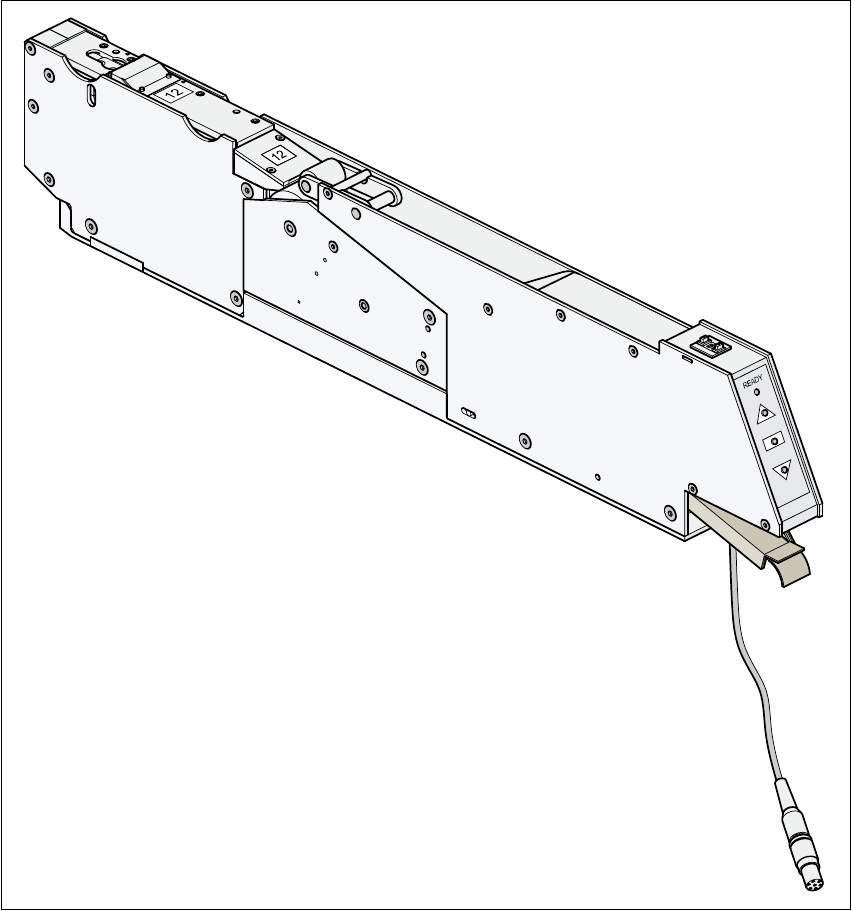
You will need the surf tape feeder module to supply the components in order to insert bare dies.
Feeder module versions are available for 8 mm tapes and 12 or 16 mm tapes. 10
Fig. 10.10 - 1 Surf tape feeder module
Use of the feeder module is described in chapter 16 of the feeder module operating instructions.10