00192662-01.pdf - 第481页
User Manual SIPLAC E F5/F5 HM 11 Station extensions /Hardware Software vers ion SR.407.xx 01/2001 US Edition 11.1 Nozzle changer for the 1 2-segment Collect&Place head 481 1 1 S t ation extensions /Hardware 1 1.1 Noz…

10 Component handling User Manual SIPLACE F5/F5 HM
10.10 Surftape feeder module (with DCA option only) Software version SR.407.xx 01/2001 US Edition
480
under power stage 14.
Power record 14 in the axis record for the Z axis concerned (SP head, IC head) is reserved
for this setting.
*3) The time required to extend the pusher needle depends on the travel of the selected pusher
needle. Check chapter 16 of the feeder module operating instructions for setting the pusher
needle travel.
10.10.4 Settings when starting for the first time
1. Set the switch options for the surf tape feeder to “1”.
2. You can select a pick-up force other than the standard force (see *2, Page 479
).
3. Modify the ‘Wait time for pusher needle‘ and ‘Foil removal time‘ feeder data to suit the feeder
type used.
4. Enter the package form numbers, specifying the wait time during placement in the package
form arrays (SP head and/or IC head) for placement from surf tape feeders.
5. You can enter a placement force other than the standard force.
10.10.5 Maintaining the DCA.MA file
1. Maintain the following feeder data for all the feeder types used:
Å ’Wait time for pusher needle‘
Å ’Foil removal time‘
2. Maintain the package form numbers, specifying the wait time during placement in the pack-
age form arrays (SP head and/or IC head) for placement from surf tape feeders.
10
10

User Manual SIPLACE F5/F5 HM 11 Station extensions /Hardware
Software version SR.407.xx 01/2001 US Edition 11.1 Nozzle changer for the 12-segment Collect&Place head
481
11 Station extensions /Hardware
11.1 Nozzle changer for the 12-segment Collect&Place
head
11.1.1 Overview
A nozzle changer for the 12-segment Collect&Place head can be installed, without loss of feeder
locations, to the left of the PCB conveyor. This enables the nozzle configuration to be changed
quickly, thus allowing the Collect&Place head to be quickly adapted to the needs of the placement
process. 11
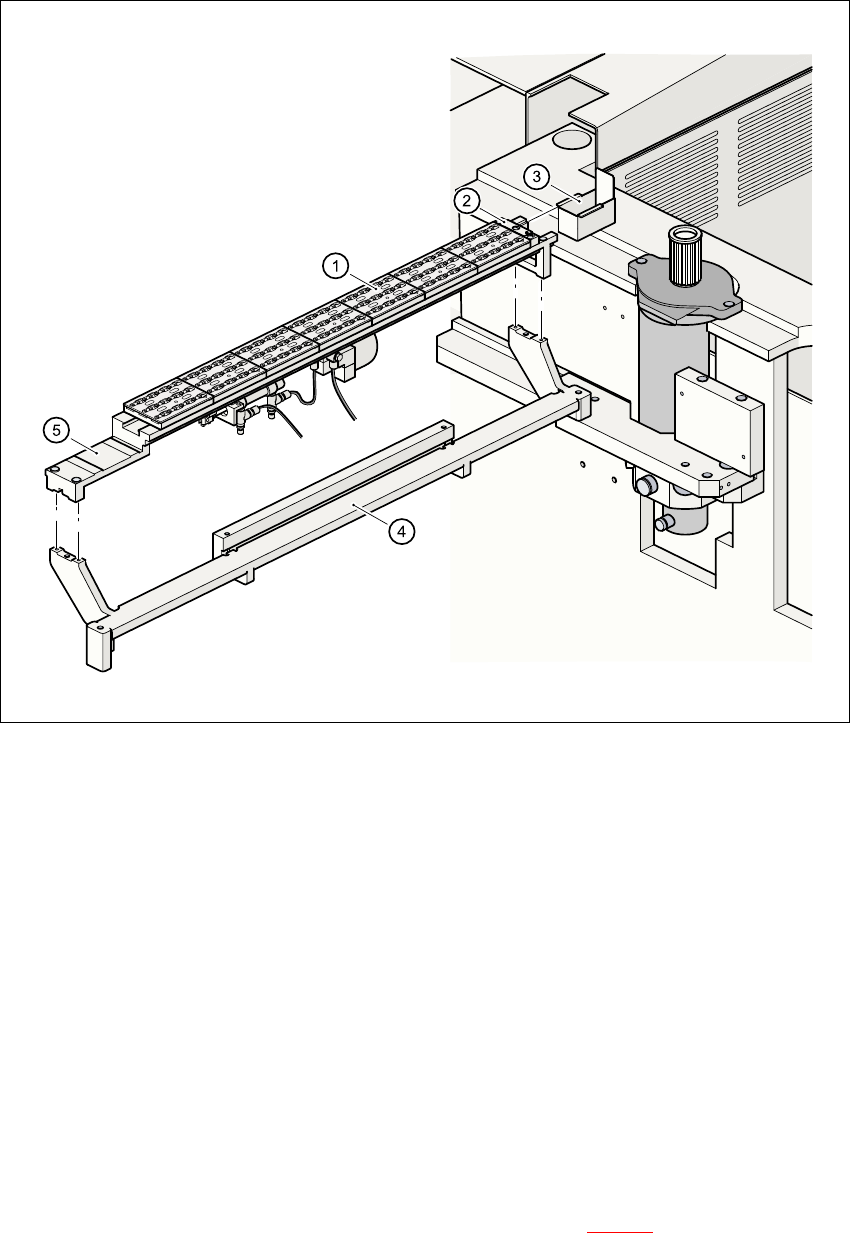
The nozzle changer consists of at least one and up to seven magazines, each with twelve nozzle
holders (see Fig. 11.1 - 1
). The magazines are mounted on a common WPC tray.Each magazine
is centered using two parallel pins, and fixed in place with a screw. 11
11.1.2 Technical data - Nozzle changer for the 12-segment Collect&Place head
11
Nozzle changer for the 12-segment Collect&Place head
Dimensions (length x width x height) 560 mm x 60 mm x 46 mm
Number of nozzle holders min.12 / max. 84
Nozzle types 9xx (F
5
HM), 7xx (F
5
)
Time required to open and close the locking plate < 200 ms
Capacity of the reject bin approx. 50 nozzles
Pneumatic system 5.3 bar air line
11 Station extensions /Hardware User Manual SIPLACE F5/F5 HM
11.1 Nozzle changer for the 12-segment Collect&Place head Software version SR.407.xx 01/2001 US Edition
482
11
Fig. 11.1 - 1 Overview of the nozzle changer for the 12-segment Collect&Place head
11.1.3 Basic principles
The nozzles are seated in nozzle holders, and are fixed in place by a movable locking plate. The
locking plate can be moved up to 6 mm by a pneumatic cylinder. All the nozzles are either clamped
or released, depending on the position of this plate. The locking plate is always left in the “closed”
position if no nozzle exchange is taking place. 11
All the nozzle changer magazines have a position fiducial for position recognition purposes. The
magazine locations on the nozzle changer are identified by numbers 1 to 7. The nozzle holders in
the magazines are numbered consecutively from 1 to 12 (see Fig. 11.1 - 3
). 11
(1) Magazine (2) Reject device for nozzles
(3) Collecting bin for rejected nozzles (4) Nozzle changer, base unit
(5) Nozzle changer, support 11