00192662-01.pdf - 第487页
User Manual SIPLAC E F5/F5 HM 11 Station extensions /Hardware Software version SR.407.xx 01/2001 US Edition 11.2 Component barcode 487 1 1 .2 Component barcode 1 1.2.1 General The placem ent mac hine allows the track ass…
11 Station extensions /Hardware User Manual SIPLACE F5/F5 HM
11.1 Nozzle changer for the 12-segment Collect&Place head Software version SR.407.xx 01/2001 US Edition
486
11.1.5 Position recognition
Every magazine has a position fiducial for position recognition purposes. 11
11
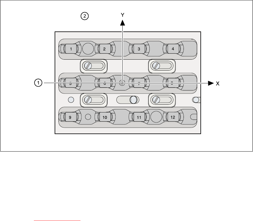
Fig. 11.1 - 3 Nozzle changer - position recognition
11
(1) Position fiducial
(2) Nozzle position in the magazine with respect to the position fiducial
11
See chapter 6
Vision functions for information on fiducial handling. 11
User Manual SIPLACE F5/F5 HM 11 Station extensions /Hardware
Software version SR.407.xx 01/2001 US Edition 11.2 Component barcode
487
11.2 Component barcode
11.2.1 General
The placement machine allows the track assignment to be checked using a barcode reader, and
the component data to be read from the component reels. 11
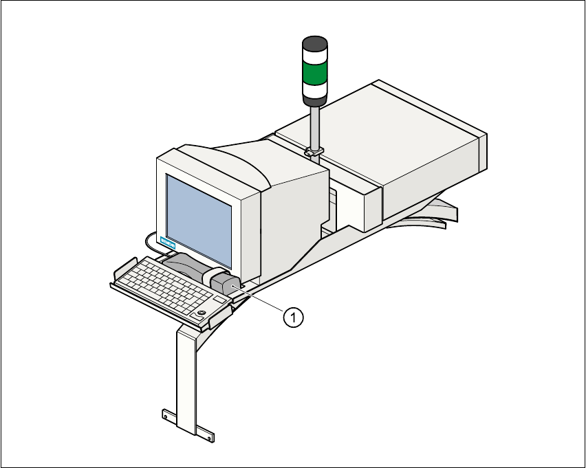
Fig. 11.2 - 1 Component barcode reader
(1) Component barcode reader
Track allocation 11
There are four-digit barcode strips on the lateral protective covers in order to identify the track al-
location. The first digit is used to identify the component feeder table (1 or 2). The other three digits
indicate the track number. Return barcodes are provided at both ends of the barcode strip. The
barcode strips are numbered consecutively in intervals of two (1, 3, 5, 7, …), and each strip is used
for 2 tracks (barcode 1 = track 1 and 2). 11
11 Station extensions /Hardware User Manual SIPLACE F5/F5 HM
11.2 Component barcode Software version SR.407.xx 01/2001 US Edition
488
Components 11
Data is read from the component reels in order to compare the stock of components with the quan-
tity required in the set-up file (refill check), for example. 11
An audible signal is given to confirm that each dataset has been read successfully. 11
PLEASE NOTE 11
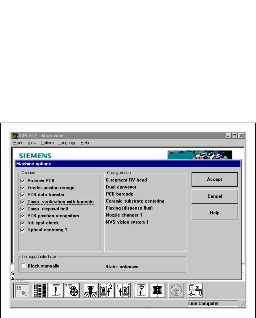
The component barcode reader option must be configured on the line computer.
Barcodes that start with number 1 or 2, and are less than 5 characters long, are interpreted as
track barcodes. All other barcodes (that do not start with number 1 or 2, and are more than 5 char-
acters long) are interpreted as component barcodes. 11
11.2.2 Notes on operation
– The barcode reader must be connected.
– The barcode must be entered on the line computer for every component.
Å To do this, select the “Set-up check with barcode” function from the Machine options menu.
Fig. 11.2 - 2 Set-up check with barcode