00192662-01.pdf - 第52页
1 Introduction and technical data User Manual SIPLACE F5/F5 HM 1.11 Overview o f the modules - controls Software version SR .407.xx 01/2001 US Edition 52 1.1 1.4 T echnica l dat a – component barcode reader 1 Fig. 1.1 1 …
User Manual SIPLACE F5/F5 HM 1 Introduction and technical data
Software version SR.407.xx 01/2001 US Edition 1.11 Overview of the modules - controls
51
1.11.3.1 Controls on the input and output conveyor sides of the machine
The controls on the input and output conveyor sides of the machine are identical. 1
Emergency stop mushroom-head push-button, Start and Stop buttons 1
There is an emergency stop mushroom-head push-button, a Start button and a Stop button on
both the input and output conveyor sides of the PCB conveyor. This arrangement was adopted for
the emergency stop mushroom-head push-buttons because it enables them to be reached quickly
and easily from any position. 1
In addition, it is important to have an unrestricted view of the placement heads and placement area
during maintenance, servicing and setting up work in order to be able to check all the operations
carried out inside the machine. This particularly important during testing phases, or when starting
single functions, for example. 1
Key switch 1
The key switch is located on the operating panel on the PCB output conveyor. It is only needed
for setting up and servicing work so, for reasons of efficiency, it is positioned near the Start and
Stop buttons. 1
Main switch 1
The main switch is part of the power supply unit, so it is positioned on the left-hand side of the
PCB input conveyor. It is located here because it is only needed for servicing and maintenance
work and is therefore not subject to frequent use. 1
1.11.3.2 Controls on the machine console
Station computer, monitor and keyboard 1
The station computer, monitor and keyboard are all mounted on the console. They are arranged
so that any person who is at least 1.60 m tall can work comfortably and efficiently. 1
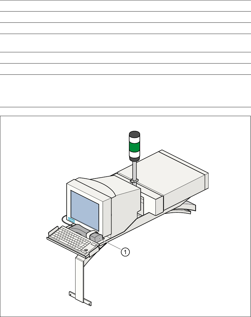
Component barcode reader 1
The two component tables for supplying components are arranged on the right and left of the ma-
chine. For this reason, the component barcode reader is also located in the central console, since
it enables the operators to work comfortably and efficiently during the set-up and refill check. 1
1 Introduction and technical data User Manual SIPLACE F5/F5 HM
1.11 Overview of the modules - controls Software version SR.407.xx 01/2001 US Edition
52
1.11.4 Technical data – component barcode reader
1
Fig. 1.11 - 2 Component barcode reader
(1) Component barcode reader
Connected to Station computer
Data entry Via barcode scanner or keyboard
Number of characters Up to 40
Not permissible Barcodes starting with a 1 or 2
and less than 5 characters long
Number of barcodes Up to 6 per component
Filter for suppressing data Up to 1 per barcode
Preset code types Code 39 (standard or ASCII)
Code 2 of 5, interleaved and normal,
Code 128, UPC/EAN/JAN codes
(others available upon request)
User Manual SIPLACE F5/F5 HM 1 Introduction and technical data
Software version SR.407.xx 01/2001 US Edition 1.12 Overview of the modules - gantry
53
1.12 Overview of the modules - gantry
1.12.1 Position of the gantry
1
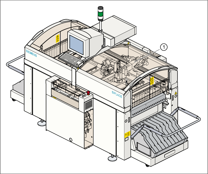
Fig. 1.12 - 1 Position of the gantry
(1) Gantry
1
The gantry system consists of two functional groups 1
– X axis and
– Y axis.
1