00192662-01.pdf - 第520页
11 Station extensions /Hardware User Manua l SIPLACE F5/F5 HM 11.8 Coplanarity laser module Software v ersion SR.407.xx 01/2001 US Ed ition 520 Fig. 1 1.8 - 5 Coplanarity laser m odule (1) Laser m odule (2) Connectin g c…
User Manual SIPLACE F5/F5 HM 11 Station extensions /Hardware
Software version SR.407.xx 01/2001 US Edition 11.8 Coplanarity laser module
519
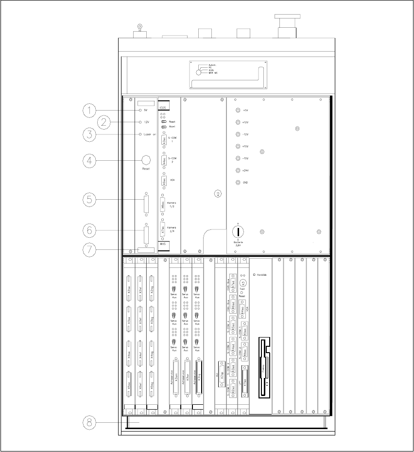
Fig. 11.8 - 4 Overview of the coplanarity laser module
(1) Green LED: 5V operating voltage
(2) Green LED: 12V operating voltage
(3) Green LED: Laser module switched on
(4) RESET key
(5) SUB-D connector, 9-pin, COM2: to the machine controller
(6) SUB-D connector, 15-pin: to the laser module
(7) Vision analysis unit with control section
(8) Control unit
11 Station extensions /Hardware User Manual SIPLACE F5/F5 HM
11.8 Coplanarity laser module Software version SR.407.xx 01/2001 US Edition
520
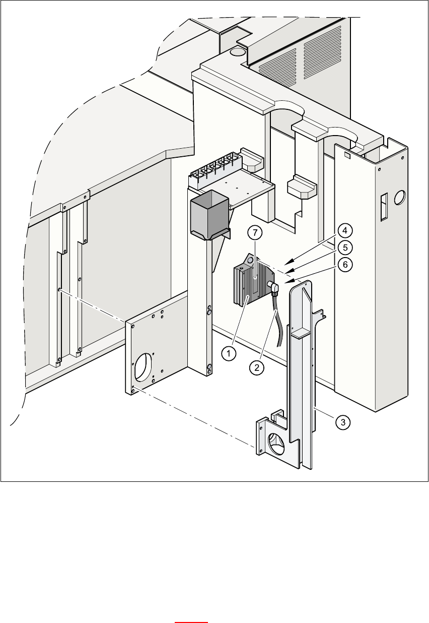
Fig. 11.8 - 5 Coplanarity laser module
(1) Laser module
(2) Connecting cable
(3) Supporting frame
(4) Red LED: OUT OF RANGE
(5) Red LED: POOR TARGET
(6) Green LED: LASER ON
(7) Class 3 B Laser Product, see Fig. 11.8 - 2

User Manual SIPLACE F5/F5 HM 11 Station extensions /Hardware
Software version SR.407.xx 01/2001 US Edition 11.8 Coplanarity laser module
521
11.8.5 Data entry
– Enter the coplanarity measurement under ‘Handling data’ in the package form editor (see sec-
tion 5.4.4 of the SIPLACE UNIX line computer user manual).
– Enter the maximum deviation from coplanarity (see max. component height tolerance, section
5.2.5 ‘NU editor functions’ of the SIPLACE UNIX line computer user manual).
PLEASE NOTE
You can activate or deactivate the coplanarity laser module from the ‘"Options" Menu
’ (see section
3.3.2.3
of this user manual). The coplanarity measurement can be switched off or on for those
components for which the coplanarity measurement is set in the package form data. 11