00192662-01.pdf - 第533页
User Manual SIPLAC E F5/F5 HM 11 Station extensions /Hardware Software version SR.407.xx 01/2001 US Edition 11.9 Flux dispenser unit 533 11 Fig. 1 1.9 - 8 Editing the fluxing packa ge form list (1) Highligh t the l ine (…

11 Station extensions /Hardware User Manual SIPLACE F5/F5 HM
11.9 Flux dispenser unit Software version SR.407.xx 01/2001 US Edition
532
Volume: 11
– The volume of flux to be applied for the current component in (µl).
– You can enter flux volumes from 1 µl to 100 µl.
– We recommend the following values as a guideline:
6 mm x 6 mm component => 8 µl flux
10 mm x 10 mm component => 10-15 µl flux
Holding time: 11
– The time for which the component must be held in the flux after placement.
– This may be set to 0 to 500/100 sec, which corresponds to 0 to 5 seconds.
Comment: 11
– Here you can enter a comment about the component.
11
Å Click on OK to confirm your input.
Å Click on Accept to save the edited package form list.
PLEASE NOTE
You can enter up to 25 package forms on the station computer. 11
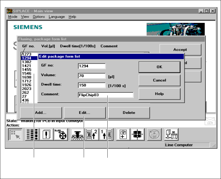
Å To edit a component, simply highlight the line containing that component (see Fig. 11.9 - 8).
Å Click on the Edit button in order to edit an existing package form.
User Manual SIPLACE F5/F5 HM 11 Station extensions /Hardware
Software version SR.407.xx 01/2001 US Edition 11.9 Flux dispenser unit
533
11
Fig. 11.9 - 8 Editing the fluxing package form list
(1) Highlight the line
(2) ‘Edit’ button
(3) Input boxes
11
Å Edit the data as described for Add.
Å Click on OK to confirm your input.
Å Click on Accept to save the edited package form list.
11
311 111 211
11 Station extensions /Hardware User Manual SIPLACE F5/F5 HM
11.9 Flux dispenser unit Software version SR.407.xx 01/2001 US Edition
534
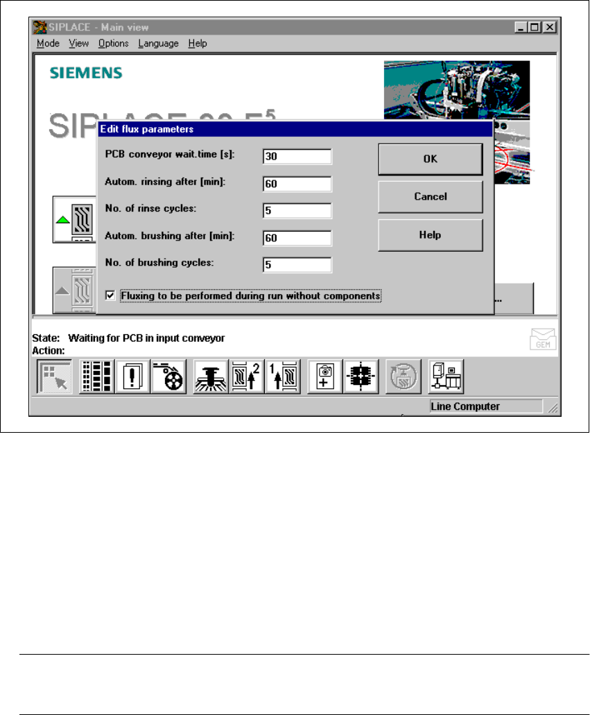
11.9.7.3 Editing the flux parameters
Å Select the “Parameters” menu to enter data for the fluxing process.
11
Fig. 11.9 - 9 Editing the flux parameters
11
Waiting time for the PCB conveyor 11
– The time for which the PCB remains in the station until it undergoes further placement. This
ensures that the flux dries reliably, and the component cannot “float away”.
– This time is measured from the last flip-chip component to be placed,
– and can be set to between 0 and 40 seconds.
PLEASE NOTE
Setting this waiting time can have a detrimental effect on line utilization. 11
11