00192662-01.pdf - 第543页
User Manual SIPLAC E F5/F5 HM 11 Station extensions /Hardware Software vers ion SR.407.xx 0 1/2001 US Edition 11.11 Feeder pos ition recognition 543 If the clu ster data co ntains an entry for a tr ack, the PCB came ra o…
11 Station extensions /Hardware User Manual SIPLACE F5/F5 HM
11.11 Feeder position recognition Software version SR.407.xx 01/2001 US Edition
542
11.11 Feeder position recognition
11.11.1 General
A feeder can be measured if it is equipped with position fiducials. 11
This function can also be used with the waffle tray holder (manual tray) if it has position fiducials. 11
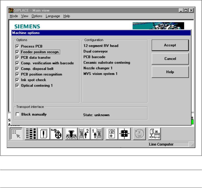
If the ‘Feeder position recognition’ function is selected on the line computer, this function will ap-
pear in the machine options. 11
You can then activate or deactivate feeder position recognition at each station from the machine
options. 11
.
Fig. 11.11 - 1 Feeder position recognition
PLEASE NOTE:
The ‘feeder position recognition’ function is always inactive when the station is switched on. 11

User Manual SIPLACE F5/F5 HM 11 Station extensions /Hardware
Software version SR.407.xx 01/2001 US Edition 11.11 Feeder position recognition
543
If the cluster data contains an entry for a track, the PCB camera on the feeder moves to the posi-
tion of the centering fiducial. Any centering fiducial offset determined by measurement is allocated
to this track, and added to the pick-up position during the pick-up process. 11
11.11.1.1 Restrictions
– Feeder position recognition cannot be used for WPC trays that are set up in the wafflepack
changer.
– Up to three fiducial positions can be defined for each feeder.
– Feeder fiducials on the right-hand side of the table (viewed in the transport direction) cannot
be measured on the 80F.
PLEASE NOTE:
This restriction does not apply to machines with a “sub-gantry camera”. 11
– If there is a feeder at location 118, and the fiducial position of the outer pick-up division is closer
to the X-axis travel range limit than the pick-up position, then the 8 mm S tape and bulk case
feeder cannot be measured.
11

11 Station extensions /Hardware User Manual SIPLACE F5/F5 HM
11.12 Nozzle changer for the 6-segment Collect&Place head Software version SR.407.xx 01/2001 US Edition
544
11.12 Nozzle changer for the 6-segment Collect&Place
head
11.12.1 Overview
A nozzle changer for the 6-segment Collect&Place head can be installed, without loss of feeder
locations, to the left of the PCB conveyor. This enables the nozzle configuration to be changed
quickly, thus allowing the Collect&Place head to be quickly adapted to the needs of the placement
process.
The nozzle changer consists of at least one and up to five magazines, each with six nozzle holders
(see Fig. 11.12 - 1
). The magazines are seated on a common support. Each magazine is centered
using two parallel pins and fixed in place with a spring hook. 11
Magazines for the 9xx (
5
HM), 7xx (F
5
) and 8xx nozzle types can be set up. The magazines can
be arranged as required. 11
11.12.2 Technical data - Nozzle changer for the 6-segment Collect&Place head
Nozzle changer for the Collect&Place head
Space required (length x width x height) 575 mm x 70 mm x 60mm
Number of nozzle holders min.6 / max.30
Possible nozzle types 7xx (F
5
); 8xx (F
5
/F
5
HM); 9xx (F
5
HM)
Opening and closing the plate < 200 ms
Capacity of the reject bin approx. 50 type 7xx / 9xx nozzles
approx. 5 type 8xx nozzles
Pneumatic system 5.3 bar air line