00192662-01.pdf - 第549页
User Manual SIPLAC E F5/F5 HM 11 Station extensions /Hardware Software version SR.407.xx 01/2001 US Edition 11 .12 Nozzle changer for the 6-segment Collect&Place head 549 1 1.12.5 Emptying t he reject bin The capacit…

11 Station extensions /Hardware User Manual SIPLACE F5/F5 HM
11.12 Nozzle changer for the 6-segment Collect&Place head Software version SR.407.xx 01/2001 US Edition
548
CAUTION 11
The magazines must not be filled until all the nozzles on the Collect&Place head have been
returned to their magazines. 11
Å See the UNIX line computer user manual for instructions on programming the nozzle changer
on the line computer.
PLEASE NOTE 11
Å Be careful not to drop components onto the magazines, since they could cause the locking
plate to jam.
Å Also avoid dropping components onto free feeder locations, since the components will stick to
the magnetic bar. The work flow may be interrupted if the feeders are not placed on the com-
ponent feeder table correctly. You should therefore regularly clean the magazines and free
locations.
User Manual SIPLACE F5/F5 HM 11 Station extensions /Hardware
Software version SR.407.xx 01/2001 US Edition 11.12 Nozzle changer for the 6-segment Collect&Place head
549
11.12.5 Emptying the reject bin
The capacity of the reject bin is approximately 50 nozzles of the 7xx/9xx nozzle type and approx-
imately 5 nozzles of the 8xx nozzle type. The reject bin must be regularly emptied in order to pre-
vent faults during the placement sequence. 11
11
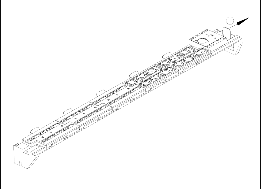
Fig. 11.12 - 3 Emptying the reject bin
(1) Remove the reject bin
11
Å Pull the reject bin out of its retainer in the direction indicated by the arrow, and lift the bin out
of its holder.
Å To return the reject bin, push it back into the retainer.
11 Station extensions /Hardware User Manual SIPLACE F5/F5 HM
11.12 Nozzle changer for the 6-segment Collect&Place head Software version SR.407.xx 01/2001 US Edition
550
11.12.6 Changing the magazine
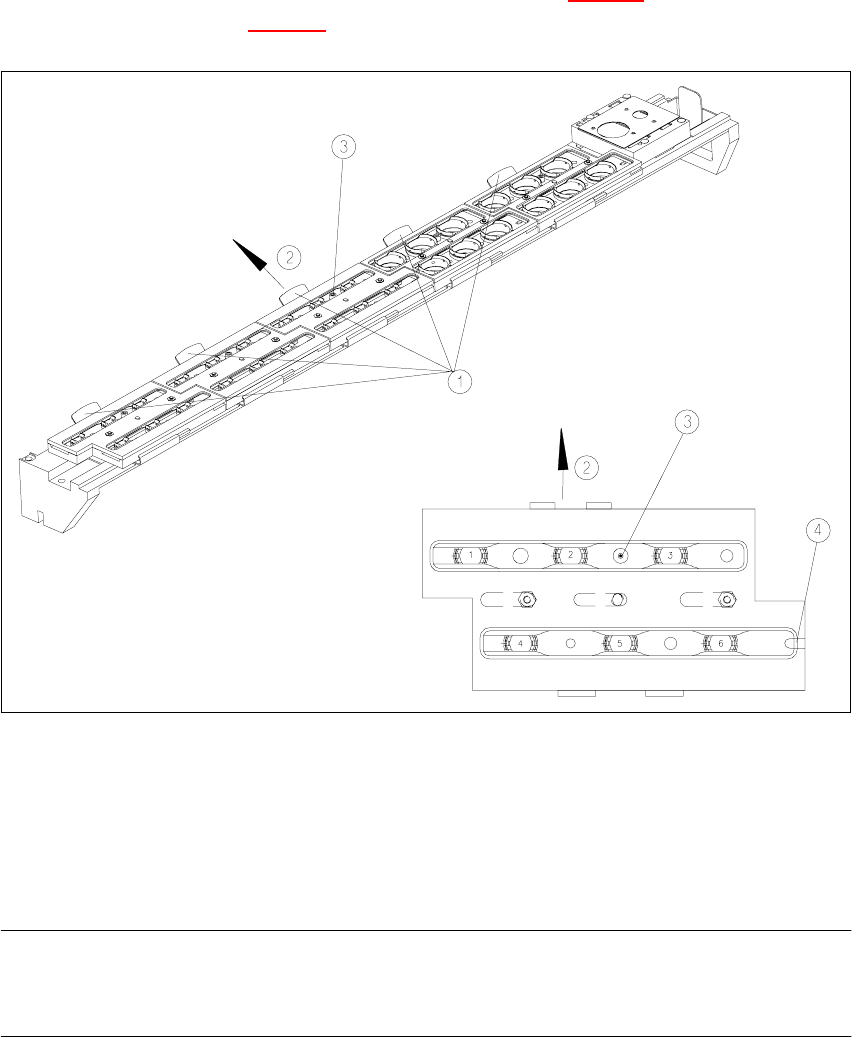
Å To remove the magazine, push the spring hook (item 1 in Fig. 11.12 - 4) to one side and lift the
magazine (item 1 in Fig. 11.12 - 4
) out of the tray.
11
Fig. 11.12 - 4 Changing the magazine
(1) Spring hook
(2) Push the spring hook to one side
(3) Position fiducial
(4) Latching groove
PLEASE NOTE
When you insert the magazine, make sure that the side with the position fiducial points towards
the spring hook. There is a latching groove on the opposite side of the magazine. 11
Å To insert the magazine, place the side with the groove on the tray.
Å Push the spring hook to one side and click the entire magazine onto the tray. Release the
spring hook.
The hook must latch into place.