00192662-01.pdf - 第55页
User Manual SIPLACE F5/F 5 HM 1 Introduction and technical data Software version SR.407.xx 01/2001 US Edition 1.12 Overview of the modules - gantry 55 1.12.3 T echnical dat a of the X axis 1.12.4 Struct ure of the Y axis…
1 Introduction and technical data User Manual SIPLACE F5/F5 HM
1.12 Overview of the modules - gantry Software version SR.407.xx 01/2001 US Edition
54
1.12.2 Structure of the X axis
1
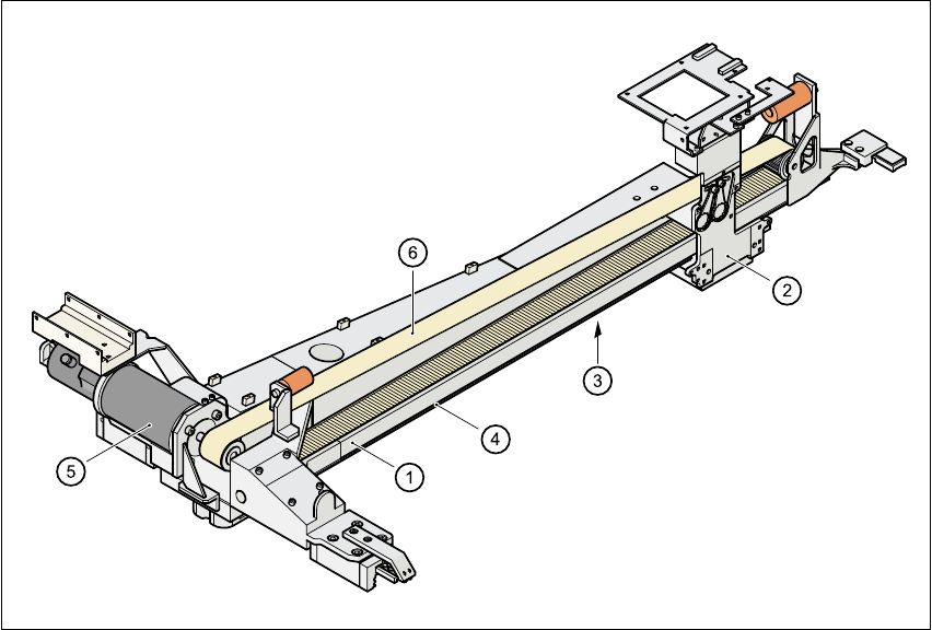
Fig. 1.12 - 2 Structure of the X axis
The x axis essentially consists of the following main modules: 1
– Gantry arm (1)
– Head mount (2)
– X axis measuring system (3)
– X axis guide system (4)
– X axis three-phase AC servomotor (5) (F
5
HM), X axis DC servomotor (F
5
)
– Toothed belt (6)
The head mount holds the following components: 1
– Sub-gantry camera (camera for the PCB vision module)
– Head board
– Measuring head for the x axis measuring system
– Revolver head

User Manual SIPLACE F5/F5 HM 1 Introduction and technical data
Software version SR.407.xx 01/2001 US Edition 1.12 Overview of the modules - gantry
55
1.12.3 Technical data of the X axis
1.12.4 Structure of the Y axis
The y axis essentially consists of the following main modules: 1
– Y axis three-phase AC servomotor (5) (F
5
HM), DC servomotor (F
5
)
– Y axis toothed belt
– Y axis guide system
– Y axis measuring system
1
Each y axis is driven by a three-phase AC servomotor. An anti-crash circuit prevents the paths of
the gantries meeting. 1
1.12.5 Technical data of the Y axis
Driving mechanism Three-phase AC servomotor/toothed belt (F
5
HM)
DC servomotor/toothed belt (F
5
)
Max. speed 2.5 m/sec.
Travel path 620 mm
Distance measuring system Linear metal scale
Scale length 646 mm
Resolution 1.0 µm (F
5
HM)
2.5 µm (F
5
)
Driving mechanism Three-phase AC servomotor/toothed belt (F
5
HM)
DC servomotor/toothed belt (F
5
)
Max. speed 2.5 m/sec.
Path of the gantries 910 mm
Distance measuring system Linear metal scales
Scale length 970 mm
Resolution 1.0 µm (F
5
HM)
2.5 µm (F
5
)
1 Introduction and technical data User Manual SIPLACE F5/F5 HM
1.13 Overview of the modules - placement heads Software version SR.407.xx 01/2001 US Edition
56
1.13 Overview of the modules - placement heads
1.13.1 Structure of the 12-segment Collect&Place head
1
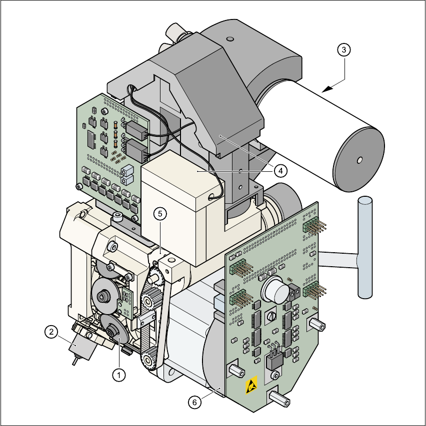
Fig. 1.13 - 1 Structure of the 12-segment Collect&Place head
All the components are inserted with the same cycle time. Before the component is inserted, it is
measured by the optoelectronic vision module. 1
(1) Star with 12 sleeves (2) Motor for "Reject" valve adjustment drive
(3) Turning station (4) Component vision module
(5) Z axis driving mechanism (6) Star motor