00192662-01.pdf - 第61页
User Manual SIPLACE F5/F 5 HM 1 Introduction and technical data Software version SR.407.xx 01/2001 US Edition 1.13 Overview of the modules - placement heads 61 1.13.8 Description of the 6-s egment Co llect&Pla ce hea…
1 Introduction and technical data User Manual SIPLACE F5/F5 HM
1.13 Overview of the modules - placement heads Software version SR.407.xx 01/2001 US Edition
60
1.13.7 Structure of the 6-segment C&P head with standard CO vision module
1
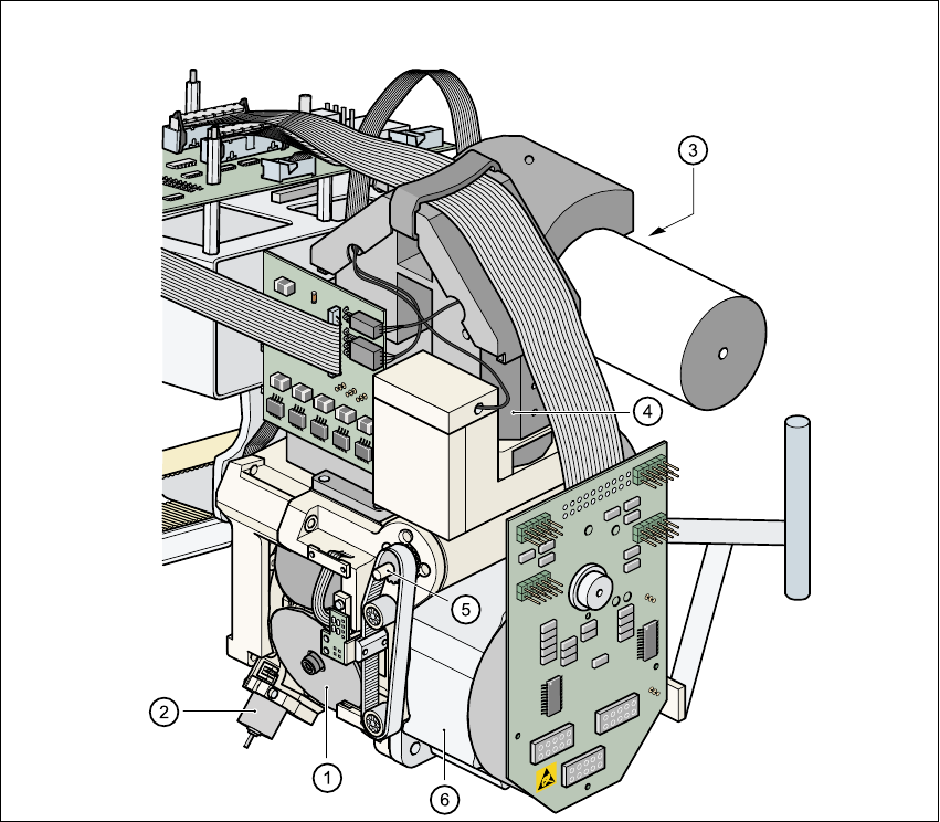
Fig. 1.13 - 3 Overview of the 6-segment Collect&Place head with standard component vision module
(1) Star with 6 sleeves
(2) Motor for "Reject" valve adjustment drive
(3) Turning station
(4) Standard vision module
(5) Z axis driving mechanism
(6) Star motor

User Manual SIPLACE F5/F5 HM 1 Introduction and technical data
Software version SR.407.xx 01/2001 US Edition 1.13 Overview of the modules - placement heads
61
1.13.8 Description of the 6-segment Collect&Place head
The functionality of the 6-segment Collect&Place head is similar to that of the 12-segment Col-
lect&Place head. With its standard vision module, the 6-segment Collect&Place head can quickly
and accurately place ICs with an edge length of up to 32mm x 32mm. It really comes into its own
when there is a very high proportion of ICs in the placement process. The cycle time of the 6-seg-
ment Collect&Place head depends on the dimensions and number of component leads or
bumps. 1
1.13.9 Technical data of the 6-segment C&P head with standard component
vision module
Component dimensions
Max. height
Max. weight
0.5mm x 1.0mm to 32mm x 32mm
8.5mm
5 g
Travel of the Z axis Max. 16 mm
Programmable placement force 2.4 to 5.0 N
Max. placement rate 8,000 components/hour
Angular accuracy ± 0.225° / 3 σ, ± 0.30° / 4 σ, ± 0.45° / 6 σ
Placement accuracy of the standard vision
module
± 52.5 µm / 3 σ, ± 70 µm / 4 σ, ± 105 µm / 6 σ
1 Introduction and technical data User Manual SIPLACE F5/F5 HM
1.13 Overview of the modules - placement heads Software version SR.407.xx 01/2001 US Edition
62
1.13.10 Structure of the 6-segment C&P head with component vision module for
flip-chips, bare dies, and standard components (DCA option)
1
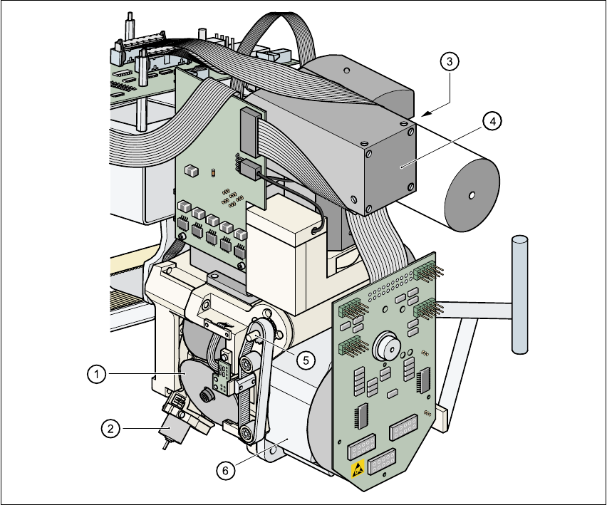
Fig. 1.13 - 4 Structure of the 6-segment C&P head with component vision module
for flip-chips, bare dies, and standard components
(1) Star with 6 sleeves
(2) Motor for "Reject" valve adjustment drive
(3) Turning station
(4) DCA vision module
(5) Z axis driving mechanism
(6) Star motor