00192662-01.pdf - 第63页
User Manual SIPLACE F5/F 5 HM 1 Introduction and technical data Software version SR.407.xx 01/2001 US Edition 1.13 Overview of the modules - placement heads 63 1.13.1 1 Description of the 6-s egment Collect&Place hea…
1 Introduction and technical data User Manual SIPLACE F5/F5 HM
1.13 Overview of the modules - placement heads Software version SR.407.xx 01/2001 US Edition
62
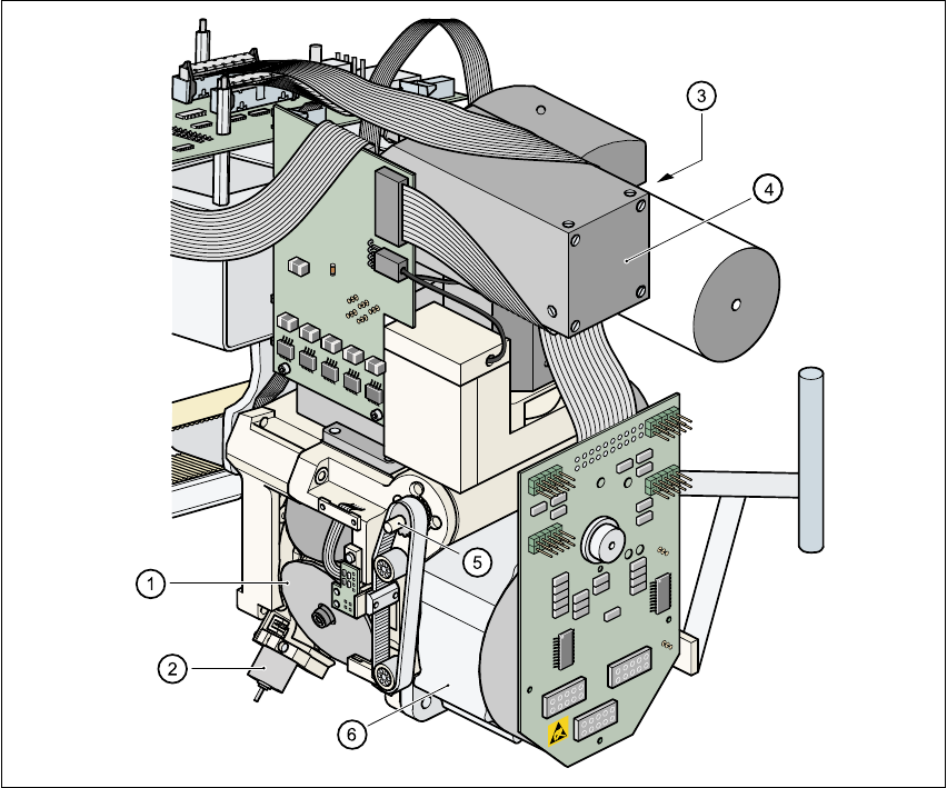
1.13.10 Structure of the 6-segment C&P head with component vision module for
flip-chips, bare dies, and standard components (DCA option)
1
Fig. 1.13 - 4 Structure of the 6-segment C&P head with component vision module
for flip-chips, bare dies, and standard components
(1) Star with 6 sleeves
(2) Motor for "Reject" valve adjustment drive
(3) Turning station
(4) DCA vision module
(5) Z axis driving mechanism
(6) Star motor

User Manual SIPLACE F5/F5 HM 1 Introduction and technical data
Software version SR.407.xx 01/2001 US Edition 1.13 Overview of the modules - placement heads
63
1.13.11 Description of the 6-segment Collect&Place head with DCA option
With the DCA vision module, the 6-segment Collect&Place head is able to optically center and
place components of the order of magnitude of 0.5mm x 0.25mm to 13mm x 13mm. The DCA
package optimizes the speed and accuracy when placing high-speed flip-chips and bare die
components. 1
1.13.12 Technical data of the 6-segment Collect&Place head with DCA option
Component dimensions
Max. height
Max. weight
0.5mm x 0.25mm to 13mm x 13mm
8.5mm
5 g
Travel of the Z axis Max. 16 mm
Programmable placement force 2.4 to 5.0 N
Max. placement rate 8,000 components/hour
Angular accuracy ± 0.225° / 3 σ, ± 0.30° / 4 σ, ± 0.45° / 6 σ
Placement accuracy of the DCA vision
module
± 45 µm / 3 σ, ± 60 µm / 4 σ, ± 90 µm / 6 σ

1 Introduction and technical data User Manual SIPLACE F5/F5 HM
1.14 Overview of the modules - vision systems Software version SR.407.xx 01/2001 US Edition
64
1.14 Overview of the modules - vision systems
Every machine has 1
– a PCB vision module on the Collect&Place head,
– a fine-pitch component vision module on the machine base, and
– a PCB vision module on the underside of the X-axis gantry
1
The vision evaluation unit is located on the machine’s control unit. The component vision module
is used to 1
– determine the precise position of the component at the nozzle, and
– the geometry of the package form.
1
The PCB vision module uses fiducials on the PCB to determine 1
– the position of the PCB,
– its rotational angle,
– and the PCB distortion.
Damaged PCBs or subpanels are marked with ink spots. The PCB vision module scans the ink
spots, and signals that these circuits should not be placed. 1
The PCB vision module also uses fiducials on the feeders to determine the precise component
pick-up position. This is particularly important for tiny components. 1
1.14.1 Technical data of the component vision module on the 12-segment C&P head
Max. component dimensions 0.5mm x 1.0mm to 18.7mm x 18.7mm
Component range
0402 to PLCC44
including BGA, µBGA, flip-chip, TSOP, QFP
PLCC, SO to SO32, DRAM
Minimum lead pitch ≥ 0.5 mm
Field of view 24mm x 24mm
Method of illumination Front lighting (3 levels programmable as required)