CP43操作手册.pdf.pdf - 第183页
FCP IV -3 Operation (2) T olerance Error Display (3) Pickup Error Display Chapter 3 Description of Commands Part 3 3 – 58 V ersion 5.0
FCP IV-3 Operation
The details of the vision trace function are explained below.
1. No. 0 Result
A graphic display is carried out based on the results of inspection. When
either the [REINSPECT] or [ACQR INSPECT] vision command is carried
out this flag will automatically be set to ON.
Details of the Inspection Results Graphic Display
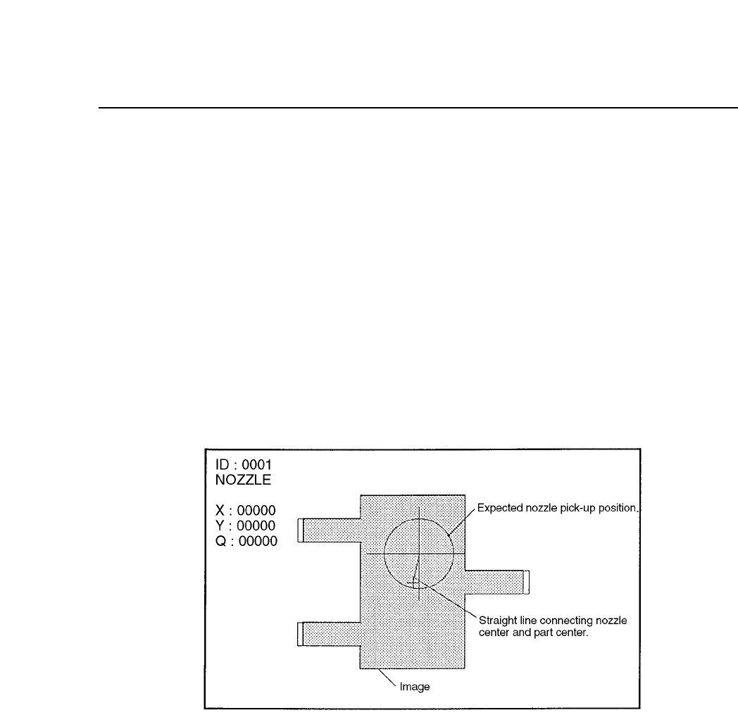
After vision processing is complete the recognized device center value is
displayed graphically. The amount of correction that is indicated by the
outline of the device shape and the nozzle position is then carried out. If
an error has occurred the details of the error will be displayed.
(1) Normal Display
Chapter 3 Description of Commands
Part 3
3 – 57
Version 5.0
FCP IV-3 Operation
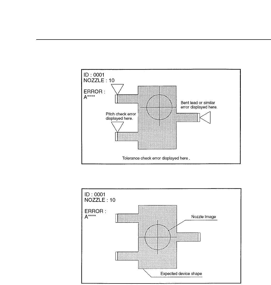
(2) Tolerance Error Display
(3) Pickup Error Display
Chapter 3 Description of Commands
Part 3
3 – 58
Version 5.0
FCP IV-3 Operation
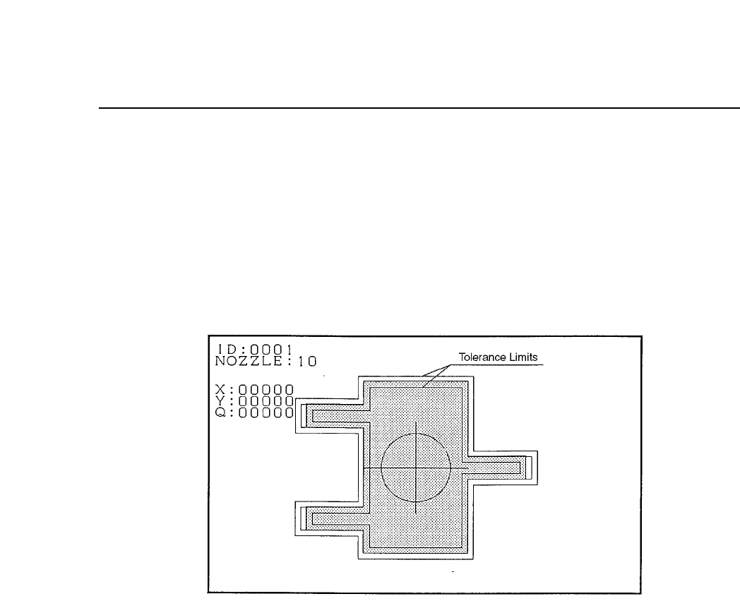
2. No. 1 Tole
A display of the inspection results graph laid over the tolerance graph is
carried out. When either the [REINSPECT] or [ACQR INSPECT] vision
command is carried out this flag will automatically be set to ON. A
graphic display of the inspection results is laid over the tolerance
information.
Tolerance Display Mode
3. No. 3 Point
In accordance with the algorithm the position and size of each
observation window will display along the entire inspection distance.
Chapter 3 Description of Commands
Part 3
3 – 59
Version 5.0