CP43操作手册.pdf.pdf - 第186页
FCP IV -3 Operation 7. No. 14 Detail All of the graphic functions are displayed along with the details of the data of each function. In this case the trackball is necessary . 8. No. 15 Pause This raises the flag when the…
FCP IV-3 Operation
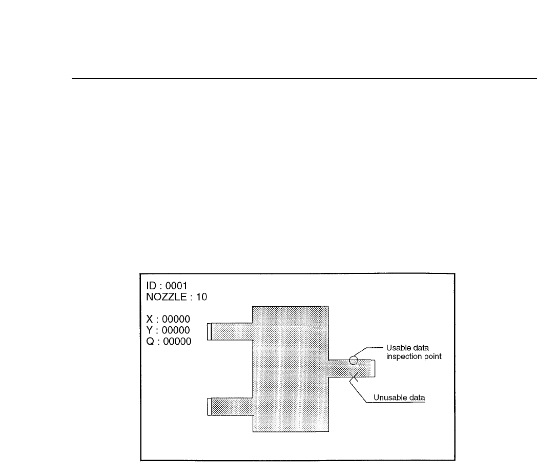
4. No. 4 Line
Display of observation points is carried out. For example, if calipers are
used then by searching for the caliper boundaries and using the
boundary points as data, the algorithm will be able to make use of these
observation points to display a graph.
If the observation point that has been found can be used as data then it
will be indicated by an [o] and if the observation point found is not
suitable foe use as data then it will be indicated by an [x].
Observation Point Display Mode
5. No. 5 Line
Display of the auxiliary observation lines is carried out. These auxiliary
observation lines can be displayed when seeking to base these lines on
the observation points. In determining the auxiliary observation lines the
observation points that are used are indicated by an [o] while the
observation points that are not used are indicated by an [x]. In addition,
the results of the angle finder and the output results of the other essential
tools are displayed for finding the blob center of gravity and the direction
of inertia of the main axis.
6. No. 13 Color
This is used to change the color of the graphic display to black. Normally
this is not set in which case the display appears in white.
Chapter 3 Description of Commands
Part 3
3 – 60
Version 5.0
FCP IV-3 Operation
7. No. 14 Detail
All of the graphic functions are displayed along with the details of the
data of each function. In this case the trackball is necessary.
8. No. 15 Pause
This raises the flag when the trackball is used. When used together with
other functions, this is used for verifying the device process while these
other functions such as zoom in or zoom out are being used.
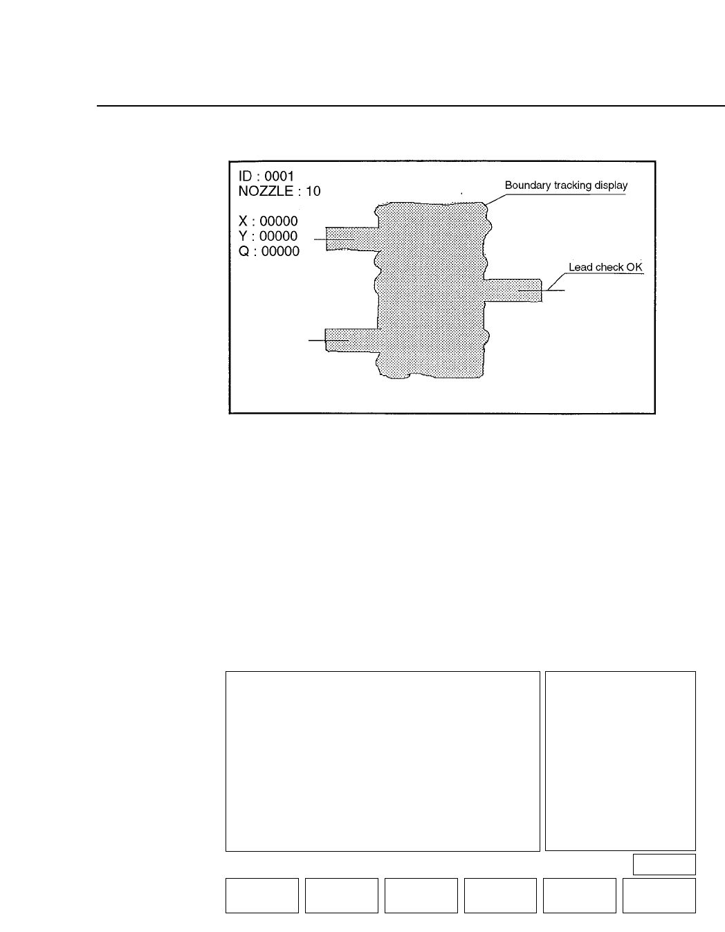
9. No. 24 Clp
This is used for verifying the device process for devices that use calipers.
This function is presently used for SOIC's and when the frontlight system
is used, for PLCC's and SQFP's.
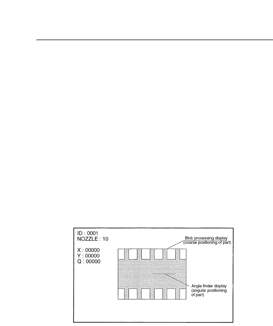
10. No. 25 Blob
This is used for process verification when the blob function is used. This
function is used for carrying out rough device positioning. This function
is presently used for SOIC's and when the frontlight system is used, for
PLCC's and SQFP's.
11. No. 26 Agf
This is used when the angle finder carries out detail verification. This
function is used when the angle or corner check is carried out during
vision processing.
Chapter 3 Description of Commands
Part 3
3 – 61
Version 5.0
FCP IV-3 Operation
12. No. 30 AcqTime
This is used for the timing of acquisition when output is being sent to a
parallel port.
13. No. 31 InsTime
This is used for the timing of inspection when output is being sent to a
parallel port.
Note: For more details concerning trace mode settings refer to Part 5, Chapter 2 of this
manual.
• First Display Area
• First Status Area
TRACE
VISION TRACE STATUS
No
0 Result OFF
1 Tole OFF
2 Window OFF
3 Point OFF
4 Line OFF
5 RS232C OFF
6 * * * * * * * *
7 * * * * * * * *
8 * * * * * * * *
9 * * * * * * * *
Mode
No Mode
10 * * * * * * * *
11 * * * * * * * *
12 * * * * * * * *
13 Color OFF
14 Detail OFF
15 Pause OFF
16 Clp OFF
17 Place OFF
18 Results OFF
19 Timers OFF
No
20 Inspect OFF
21 * * * * * * * *
22 * * * * * * * *
23 * * * * * * * *
24 Clp * * *
25 Blob OFF
26 Agf OFF
27 BT OFF
28 * * * * * * * *
29 * * * * * * * *
30 Acqtime OFF
31 Instime OFF
select No
▲▼ON / OFF QTY.CLEAR THROUGH RETURN
PAGE 522
Operation : FRONT
Ready
Chapter 3 Description of Commands
Part 3
3 – 62
Version 5.0