CP43操作手册.pdf.pdf - 第297页
Chapter 1 T race Mode Part 5 No. 30 AcqT ime This is used for the timing of acquisition when output is being sent to a parallel port. No. 31 InsT ime This is used for the timing of inspection when output is being sent to…
Chapter 1 Trace ModePart 5
No. 14 Detail
All of the graphic functions are displayed along with the details of
the data of each function. In this case the trackball is necessary.
No. 15 Pause
This raises the flag when the trackball is used. When used together
with other functions, this is used for verifying the device process
while these other functions such as zoom in or zoom out are being
used.
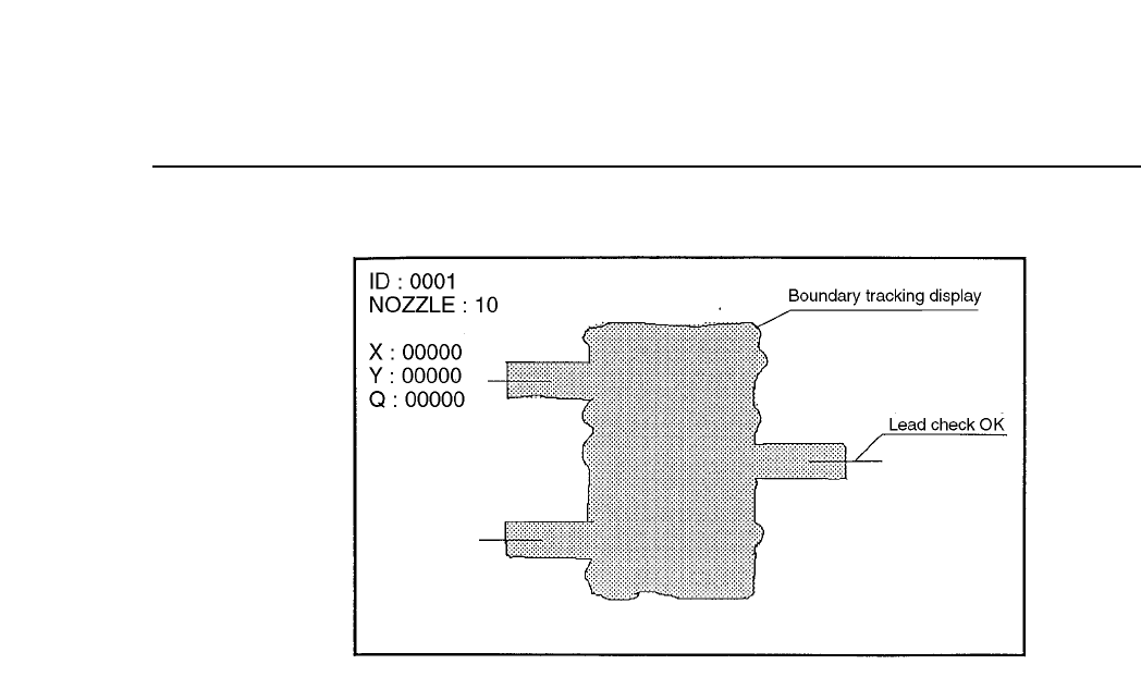
No. 24 Clp
This is used for verifying the device process for devices that use
calipers. This function is presently used for SOIC's and when the
frontlight system is used, for PLCC's and SQFP's.
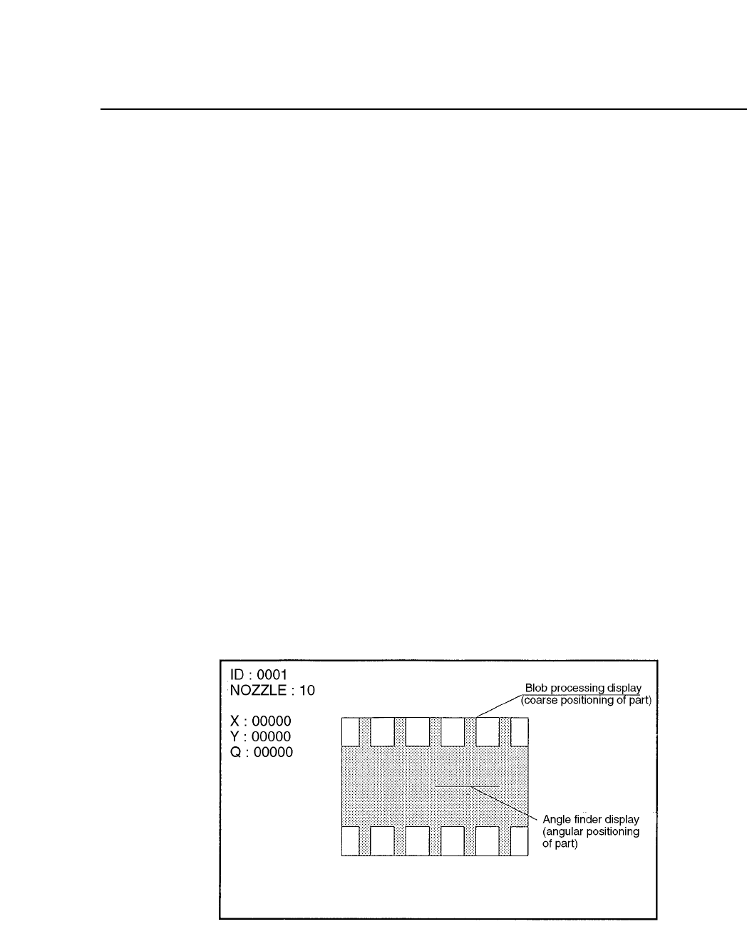
No. 25 Blob
This is used for process verification when the blob function is used.
This function is used for carrying out rough device positioning.
This function is presently used for SOIC's and when the frontlight
system is used, for PLCC's and SQFP's.
No. 26 Agf
This is used when the angle finder carries out detail verification.
This function is used when the angle or corner check is carried out
during vision processing.
5 – 7Version 2.0
Chapter 1 Trace ModePart 5
No. 30 AcqTime
This is used for the timing of acquisition when output is being sent
to a parallel port.
No. 31 InsTime
This is used for the timing of inspection when output is being sent
to a parallel port.
5 – 8Version 2.0

Chapter 2 Bright SettingPart 5
2. Bright Setting
The bright setting allows the image acquisition conditions to be adjusted for the
mark camera and the parts cameras (wide view and narrow view). The
following 2 values make up the bright setting.
2.1 Gain
This is the value for adjusting the contrast (difference in brightness).
Once the image has been acquired for vision processing the gain
determines the magnification of the video signal from the camera.
Increasing this value increases the brightness of the image. However,
caution should be taken since setting the magnification too high will lead
to the amplification of noise as well.
The range of the gain level is 0 ~ 255.
2.2 Offset
This is the value for adjusting the brightness of the entire image.
The offset level is determined when the video signal is at 0. Increasing
this value will make the image darker. Since noise will also be amplified
when the gain is raised, it is also necessary to adjust this offset value to
match the gain.
The range of the offset level is 0 ~ 255.
Note: It should be pointed out that there is almost no reason for which it should
be necessary to change the bright setting in order to be able to vision
process a fiducial mark or a part. However, if for some unforeseen reason
the camera reproduction is bad or the brightness of the mark on the board
is bad then this bright setting may be useful.
Refer to chapter 3 for details on the procedure for setting these values.
5 – 9Version 2.0