CP43操作手册.pdf.pdf - 第33页
Part 1 Chapter 4 The Display 4.2 First Display Area The display on the monitor differs depending on whether or not the user is in automatic operation mode. 4.2.1 Display During Automatic Operation Mode (a) This area disp…

Chapter 4 The DisplayPart 1
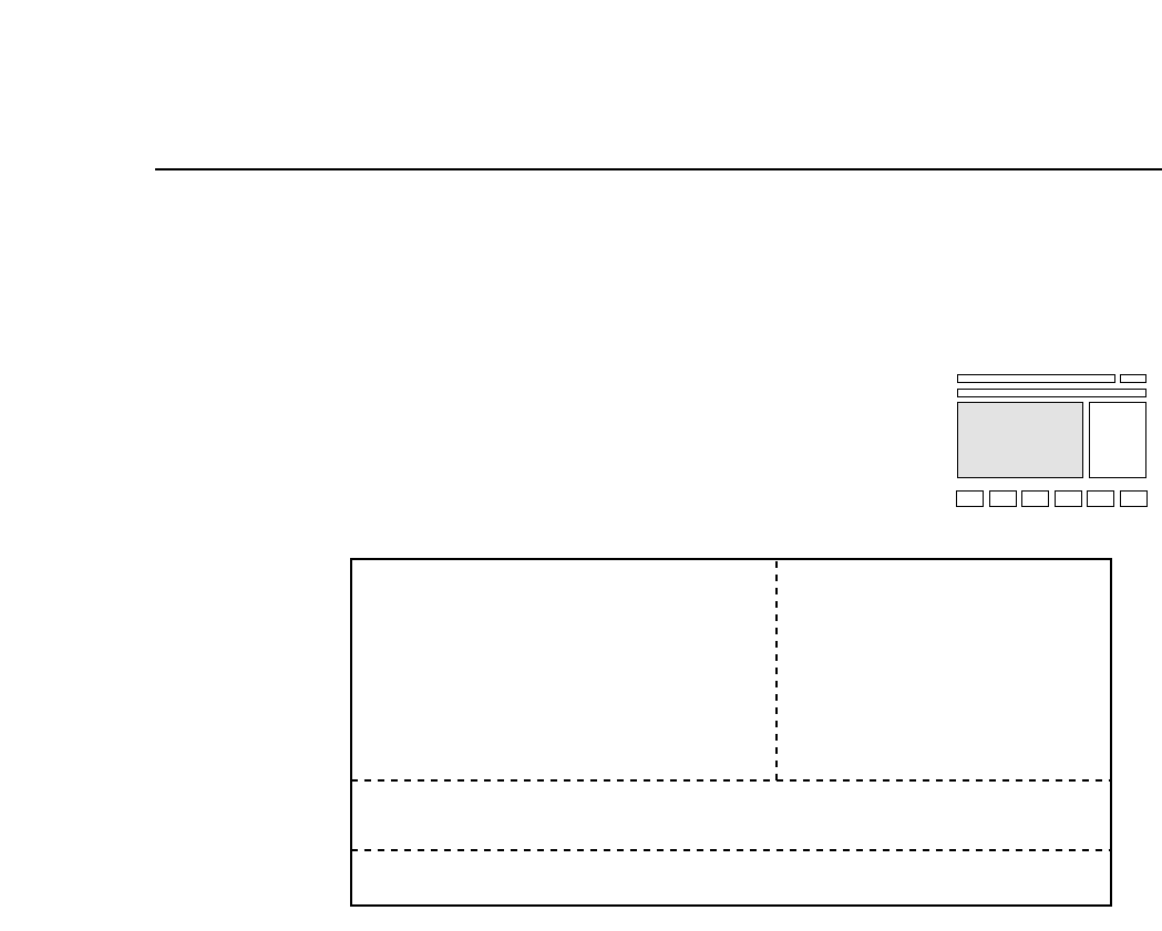
(f) First Status Area
This area displays the current command status. Command names
such as AUTO, LOADER, and SET appear here.
(g) First Display Area
This area displays information about the machine. Details regarding
the information displayed in this area are presented in Section 5.2.
(h) Second Display Area
This area displays error messages and comments to the operator.
Details regarding the information displayed in this area are presented
in Section 5.3 below.
(i) Second Status Area
This area displays additional comments that supplement the
information displayed in the First Status Area. Input from the
numerical keypad is also displayed here.
(j) Program counter
This counter is referred to when an abnormality occurs in operation of
the FCP IV-3. This counter is not referred to during normal operation.
(k) Inching axes
This display indicates which axes are currently selected for inching.
(l) Command page
The function key command page number is displayed here.
(m) Function key menu
The function keys (F1 through F6) are pressed to select commands.
Each function key corresponds to a command in the function key
menu portion of the FCP IV-3 display. To execute a command, press
the corresponding function key.
1 – 19
Version 5.0
FCP IV-3 Operation
Part 1 Chapter 4 The Display
4.2 First Display Area
The display on the monitor differs depending on whether or not the user
is in automatic operation mode.
4.2.1 Display During Automatic Operation Mode
(a) This area displays sequence information. The following
examples show how the First Display Area might appear.
ST7.N 1 D 35 This is the placing sequence number at
station 7. The device number is also
displayed.
ST7.N 1 D 35 Skip In this sequence this nozzle is being
skipped.
ST7.N 1 Fidu Fiducial marks are being read.
ST7.N 1 Blok Block skip marks are being read.
Note: In Changeover mode and Device Change mode, when Device
Table 2 (81-160) is the original table, the device positions will
be displayed as 1-80. Note that when the next device is being
used, the machine will display the actual device number, (as
opposed to the device number which has been coded in the
program).
ST7.N 1 D 35
STATUS
P Mode Product
Recovery 3 times
T Mode Joint
Clearing OFF Machine
NEXT PROD: TEST PROGRAM 1
(a)
(b)
(c)
(d)
1 – 20Version 5.0
FCP IV-3 Operation

Chapter 4 The DisplayPart 1
(b) The operation modes are displayed here.
P Mode: This item indicates whether the machine is
currently in Product, Simulate, or Idle operation
mode.
Product The machine is in normal production mode.
Simulate The machine performs a simulate operation. The
next board will be fed and axes X, Y, D1 and D2
will move according to the placing sequence.
Idle The machine does not feed boards or perform
vision processing. Otherwise, it is the same as
Product mode. In this mode, do not mount tape
feeders onto the table.
Recovery: This item indicates which of the three recovery
modes (E Pass, E Stop, or N times) the machine is
currently using.
n times The number of times that recovery is repeated can
be set. Refer to Part 3, Chapter 3 for a more
detailed explanation.
Error Stop When an error occurs the machine stops and
recovery is then carried out on the part when the
machine is started again.
Error Pass When an error occurs, the machine does not stop
and no recovery is carried out.
1 – 21
Version 5.0
FCP IV-3 Operation