CP43操作手册.pdf.pdf - 第47页
Part 1 The 6 axes are set in the following or der: X, Y , C, D1, D2, Z. During zero setting a display like the one shown below will appear in the second display area. After zero setting is complete, the D1 and D2 axes ta…
Part 1
5. Zero Setting
This chapter describes the zero setting procedure.
Servomotors control the position of each of the FCP IV-3’s six axes (X, Y, C, D1,
D2 and Z). The positions of these axes are cleared from the machine’s memory
whenever the power is turned off; therefore, the machine must determine the
position of each axis each time the power is turned on. The procedure used to
do this is known as zero setting.
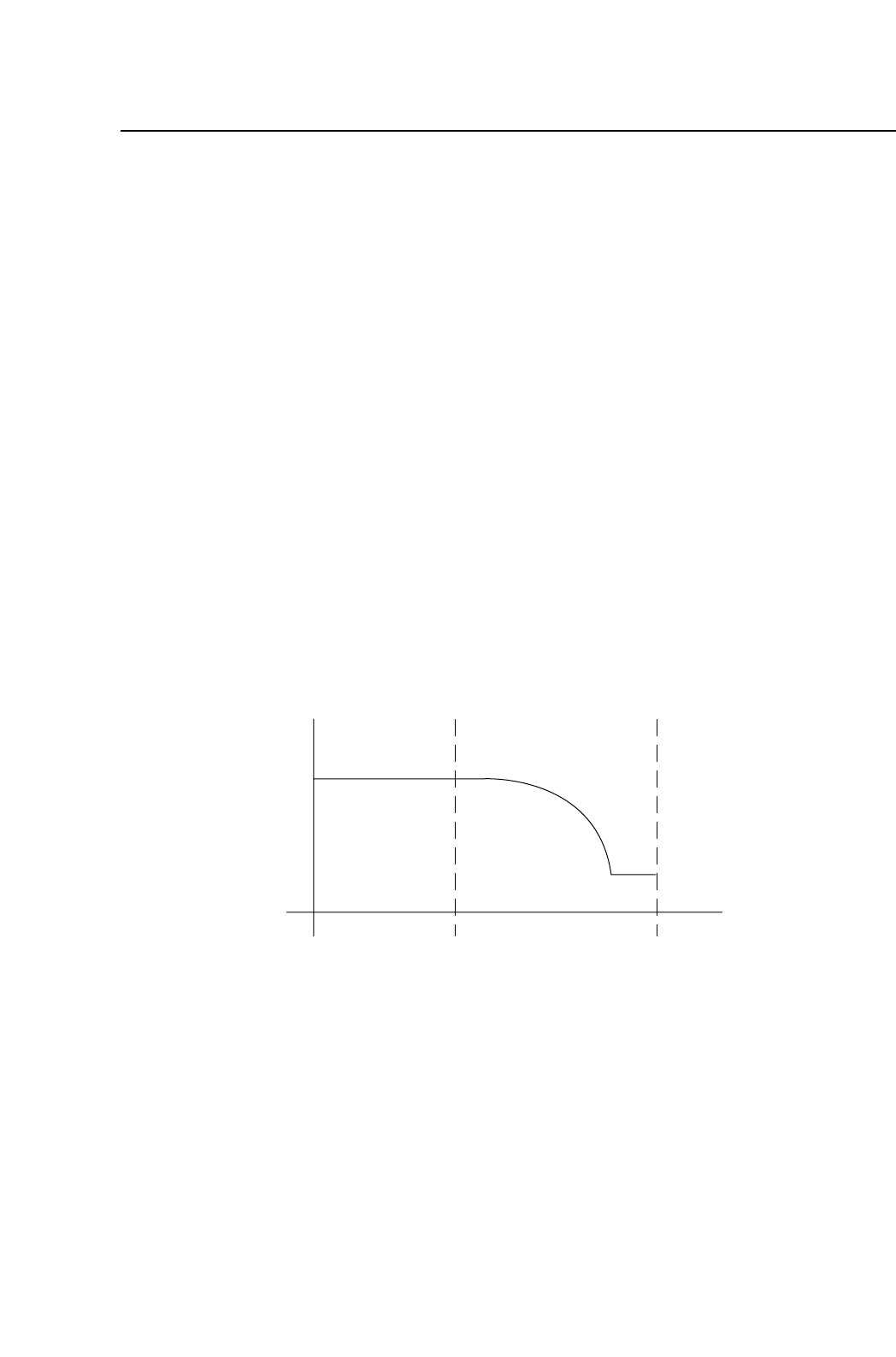
The method of zeroing an axis is described below, using the X axis as an
example.
(1) If the X-axis deceleration-point sensor input is ON, the axis initially moves
in the negative (-X) direction until this input turns OFF.
(2) The X axis moves in the positive (+X) direction and decelerates when the
X-axis deceleration-point sensor turns ON.
(3) After deceleration, the X axis inches in the positive (+X) direction.
(4) The X axis stops moving when the encoder outputs the Z signal. (The Z
signal is output only once per motor revolution.) This X-axis position
becomes the zero position.
Note: Zero setting is not performed on the FQ axis.
Speed
X-axis deceleration-point
Z signal
X+X-
1 – 33
FCP IV-3 Operation
Chapter 5 Zero Setting
Version 4.0

Part 1
The 6 axes are set in the following order: X, Y, C, D1, D2, Z. During zero setting
a display like the one shown below will appear in the second display area.
After zero setting is complete, the D1 and D2 axes tables will move to their
respective resupply positions and the shutters will then lower.
Zero Set
1 – 34
FCP IV-3 Operation
Chapter 5 Zero Setting
Version 4.0
Part 1
6. Basic Operation
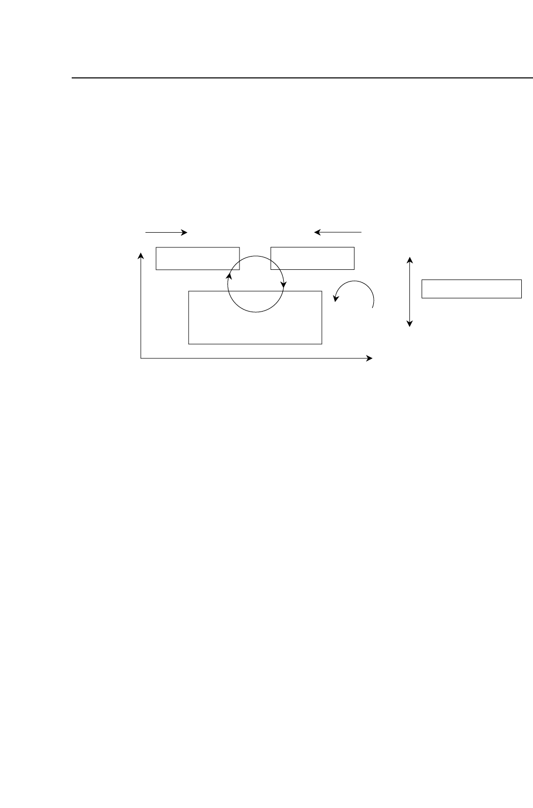
6.1 Definition of Coordinates
The FCP IV-3 coordinate system is defined in the picture below. These
coordinates are used in displays, Proper data, and programming.
6.2 Definition of Parts
6.2.1 Definition of Device Tables
The FCP IV-3 has two device (D-axis) tables, which are defined as
follows:
Table 1: The right-hand device table, as viewed from the
front of the machine.
Table 2: The left-hand device table, as viewed from the
front of the machine.
6.2.2 Original Table
The original table (that is, the device table which is used first in the
changeover and device change modes) is selected automatically
when a new production program or table mode is selected.
When in changeover mode, if the original table designated in the
program does not change, the set device table becomes the original
table.
Device Table 2
Index
Fine Theta
XY table
D2+ D1-
Y+
X+
+
+
View from top
Device Table 1
Z+
Z-
XY table
View from front
1 – 35
FCP IV-3 Operation
Chapter 5 Zero Setting
Version 4.0