CP43操作手册.pdf.pdf - 第49页
Part 1 6.2.3 Definition of Device Numbers The FCP IV -3 has three device table modes. The valid device numbers in each mode are listed below . • Joint mode (Joint) The two tables with 80 devices each move jointly to allo…
Part 1
6. Basic Operation
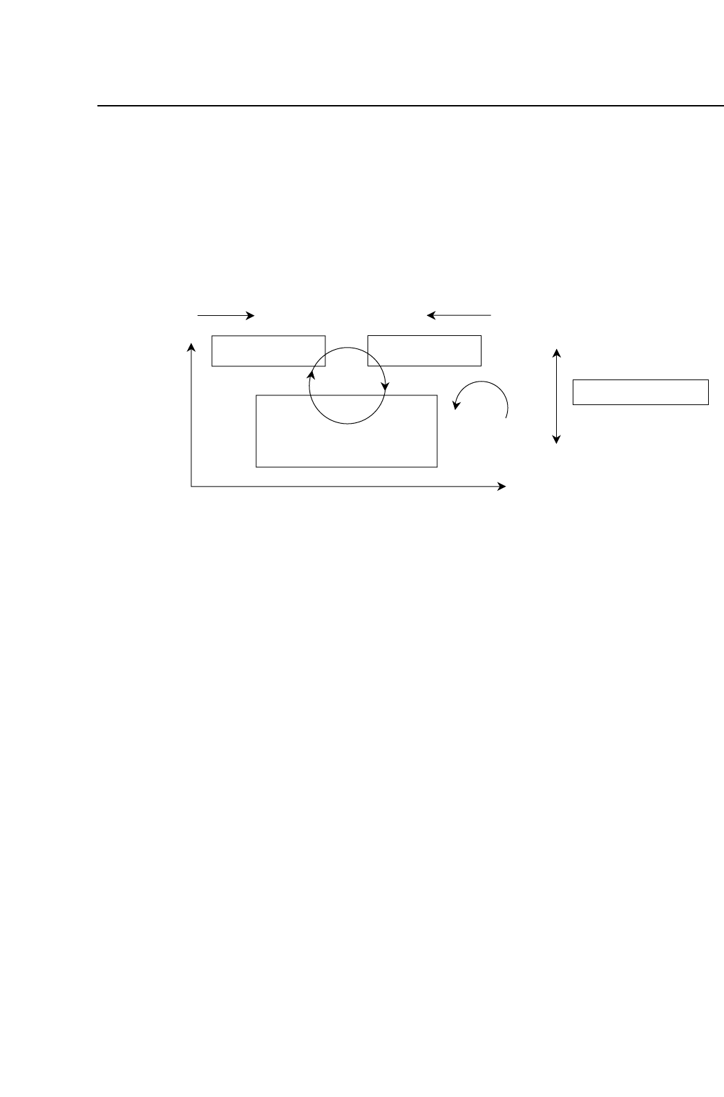
6.1 Definition of Coordinates
The FCP IV-3 coordinate system is defined in the picture below. These
coordinates are used in displays, Proper data, and programming.
6.2 Definition of Parts
6.2.1 Definition of Device Tables
The FCP IV-3 has two device (D-axis) tables, which are defined as
follows:
Table 1: The right-hand device table, as viewed from the
front of the machine.
Table 2: The left-hand device table, as viewed from the
front of the machine.
6.2.2 Original Table
The original table (that is, the device table which is used first in the
changeover and device change modes) is selected automatically
when a new production program or table mode is selected.
When in changeover mode, if the original table designated in the
program does not change, the set device table becomes the original
table.
Device Table 2
Index
Fine Theta
XY table
D2+ D1-
Y+
X+
+
+
View from top
Device Table 1
Z+
Z-
XY table
View from front
1 – 35
FCP IV-3 Operation
Chapter 5 Zero Setting
Version 4.0

Part 1
6.2.3 Definition of Device Numbers
The FCP IV-3 has three device table modes. The valid device
numbers in each mode are listed below.
•Joint mode (Joint)
The two tables with 80 devices each move jointly to allow the
use of up to 160 devices.
Valid device numbers: 1 - 160
•Device change mode (AA)
One device table is used as the spare table for the other table.
Valid device numbers: 1 - 80
Note: In this mode, identical parts must be mounted on each of the two
tables.
•Changeover mode (AB)
Only one device table operates at any one time. The other
table stays at the parts supply position to permit parts for the
next production process to be mounted.
Valid device numbers: 1 - 80
Note: Production programs specifying device numbers greater than 80
cannot be selected in the device change mode or changeover mode.
Operation is not possible if such a program is selected.
If a device number greater than 160 is included in a production
program, an error (Max D No. Error) occurs when the program is
transmitted to the machine.
1 – 36
FCP IV-3 Operation
Chapter 6 Basic Operation
Version 4.0
Part 1
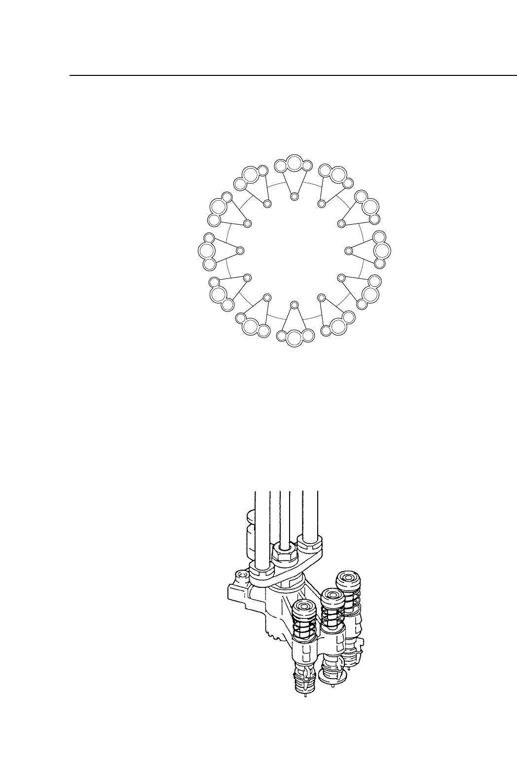
6.2.4 Functions of Each Station
The twelve placing heads, labelled A to L, form twelve stations
which rotate clockwise.
Each station has three heads: a large, medium and small nozzle, for
picking up large, medium and small parts. These nozzles are held
in place by nozzle holders, as shown in the illustration above.
Each head is located at a station, numbered 1 through 12. The
functions of each station are listed below:
L
M
S
L
M
S
L
M
S
L
M
S
L
M
S
L
M
S
L
M
S
L
M
S
L
M
S
L
M
S
L
M
S
L
M
S
ST1
ST12
ST11
ST10
ST9
ST8
ST7
ST6
ST5
ST4
ST3
ST2
B
A
C
D
E
F
G
H
I
J
K
L
1 – 37
FCP IV-3 Operation
Chapter 6 Basic Operation
Version 4.0