CP43操作手册.pdf.pdf - 第50页
Part 1 6.2.4 Functions of Each Station The twelve placing heads, labelled A to L, form twelve stations which rotate clockwise. Each station has three heads: a lar ge, medium and small nozzle, for picking up large, medium…

Part 1
6.2.3 Definition of Device Numbers
The FCP IV-3 has three device table modes. The valid device
numbers in each mode are listed below.
•Joint mode (Joint)
The two tables with 80 devices each move jointly to allow the
use of up to 160 devices.
Valid device numbers: 1 - 160
•Device change mode (AA)
One device table is used as the spare table for the other table.
Valid device numbers: 1 - 80
Note: In this mode, identical parts must be mounted on each of the two
tables.
•Changeover mode (AB)
Only one device table operates at any one time. The other
table stays at the parts supply position to permit parts for the
next production process to be mounted.
Valid device numbers: 1 - 80
Note: Production programs specifying device numbers greater than 80
cannot be selected in the device change mode or changeover mode.
Operation is not possible if such a program is selected.
If a device number greater than 160 is included in a production
program, an error (Max D No. Error) occurs when the program is
transmitted to the machine.
1 – 36
FCP IV-3 Operation
Chapter 6 Basic Operation
Version 4.0
Part 1
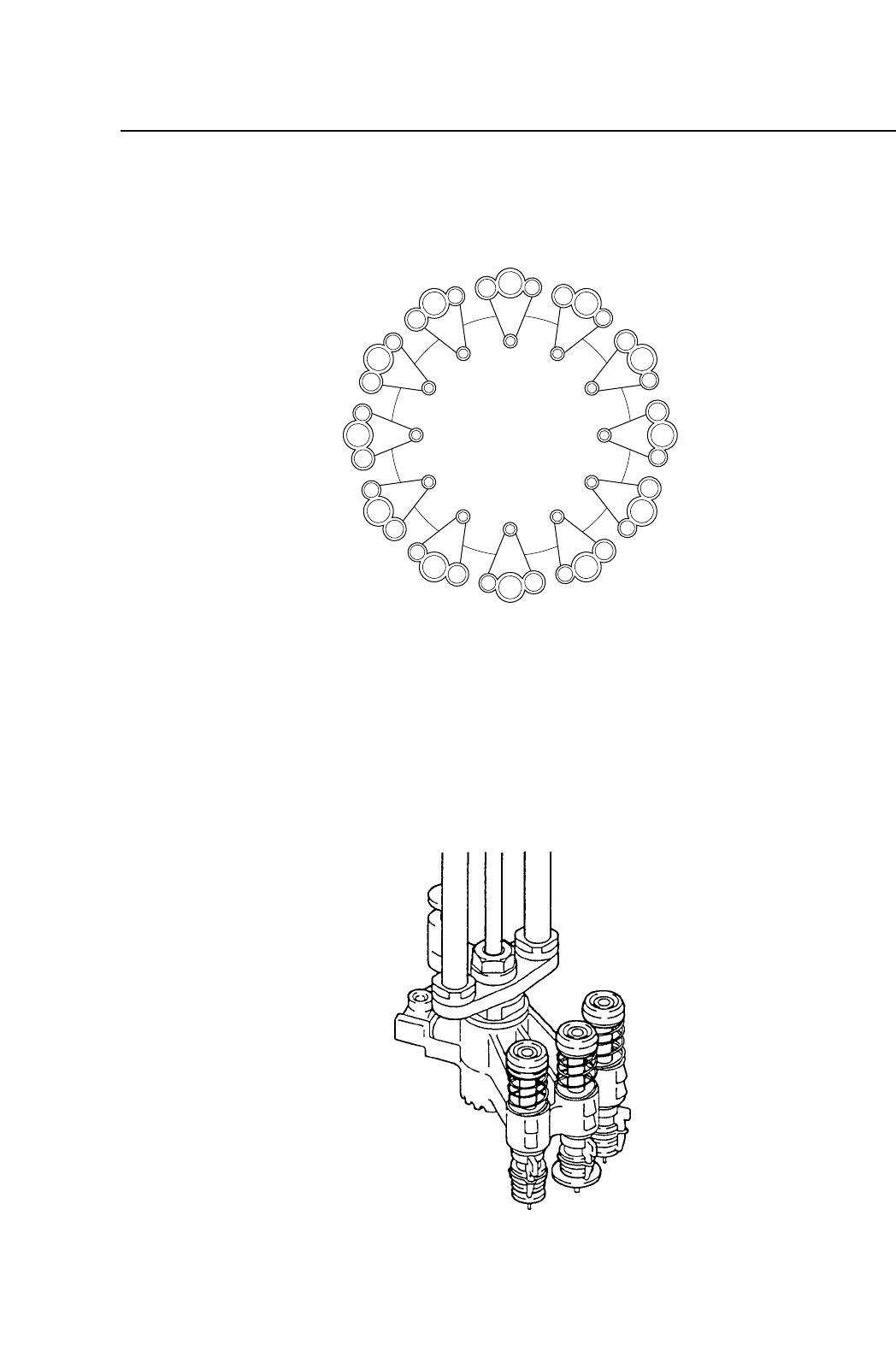
6.2.4 Functions of Each Station
The twelve placing heads, labelled A to L, form twelve stations
which rotate clockwise.
Each station has three heads: a large, medium and small nozzle, for
picking up large, medium and small parts. These nozzles are held
in place by nozzle holders, as shown in the illustration above.
Each head is located at a station, numbered 1 through 12. The
functions of each station are listed below:
L
M
S
L
M
S
L
M
S
L
M
S
L
M
S
L
M
S
L
M
S
L
M
S
L
M
S
L
M
S
L
M
S
L
M
S
ST1
ST12
ST11
ST10
ST9
ST8
ST7
ST6
ST5
ST4
ST3
ST2
B
A
C
D
E
F
G
H
I
J
K
L
1 – 37
FCP IV-3 Operation
Chapter 6 Basic Operation
Version 4.0

Part 1
• STN 1: Parts Pickup
Parts are picked from the feeder tape.
• STN 2: Large Parts Pickup Check
This station inspects large parts.
• STN 3: Pθ (Pre Theta)
Picked parts are checked to confirm that their theta orientation
is roughly where it should be, and rough corrections are made,
as follows:
Parts Orientation Corrective Rotation Angle
0˚ ~ 45˚ 0˚
45˚ ~ 180˚ 90˚
180˚ ~ 315˚ -90˚
315˚ ~ 0˚ 0˚
Further adjustments are made at station 6.
• STN 4: Inspection
The part is inspected and the corrections are computed.
• STN 5: No Function
• STN 6: Fθ (Fine Theta)
Using the calculations derived from the image in station four,
in conjunction with the coordinates obtained from reading the
fiducial marks on the board, final adjustments are made in
positioning the part.
• STN 7: Parts Placement
Using the previously obtained coordinate data, the part is
placed on the board.
• STN 8: No Function
• STN 9: Nozzle Check
The nozzle position in the Z axis is checked to ensure that the
nozzle has returned to its raised position.
• STN 10: Reject Parts Dump and Nozzle Position Check
Parts deemed by the vision system as defective or outside
dimensional tolerances are dumped at this station into the
reject box. The nozzle which was used is checked here also.
1 – 38
FCP IV-3 Operation
Chapter 6 Basic Operation
Version 4.0