CP43操作手册.pdf.pdf - 第91页
Chapter 1 Automatic Operation Part 2 1.19 Backlight and Frontlight V ision processing is carried out at Station 4. This pr ocess uses a backlight, but an optional frontlight is also available. See the Maintenance Manual …
Chapter 1 Automatic OperationPart 2
1.17 Pass Mode
If the board loaded from the previous stage does not need parts placed,
the machine can be set to let the board pass through. The two ways of
carrying out Pass mode are described below.
• Set Production_mode in the program to Pass.
• Press the [SET], [STATUS] and [PASS] command function keys, in that
order.
If Pass Mode was set in Production_mode in the program then the
message “Pass” will display in yellow on the screen. If Pass mode was set
using the command keys then the message "Pass" will display in cyan. If
“Pass” mode was set in the program it can only be cancelled using the
command function keys.
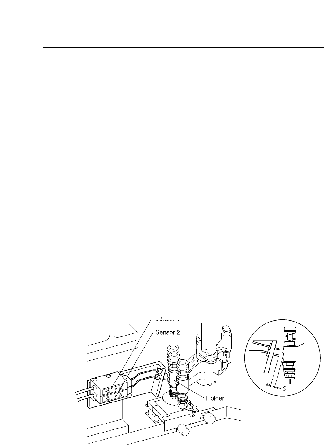
1.18 Nozzle Type and Nozzle Holder Check
At Station 10 a sensor will check to see which nozzle is being used in
order to determine whether or not nozzle change is necessary for the next
part to be picked. At Station 12, another nozzle change check sensor will
check to see if the appropriate change has been made.
2 – 22Version 2.0
FCP IV-3 Operation
Nozzle
Sensor 1
Sensor 2
S
Green unlit Green lit
L
Green lit Green lit
M
Green lit Green unlit

Chapter 1 Automatic OperationPart 2
1.19 Backlight and Frontlight
Vision processing is carried out at Station 4. This process uses a backlight,
but an optional frontlight is also available. See the Maintenance Manual
for details.
Details on setting the light type in Proper and Part data follow:
[Proper]
126. Front Light : This determines whether or not a front light is
being used.
Non : Not in use
Use : In use
When using a standard machine always set this to Non.
[Part data]
Vision_data
13. Lighting : This item selects which surface will be lit by image
processing.
Back_Light Back light in use (standard setting)
Front_Light Front light in use
When using the Front_Light setting, be sure to also
set Proper data item 126 to Use.
2 – 23Version 2.0
FCP IV-3 Operation
Chapter 1 Automatic OperationPart 2
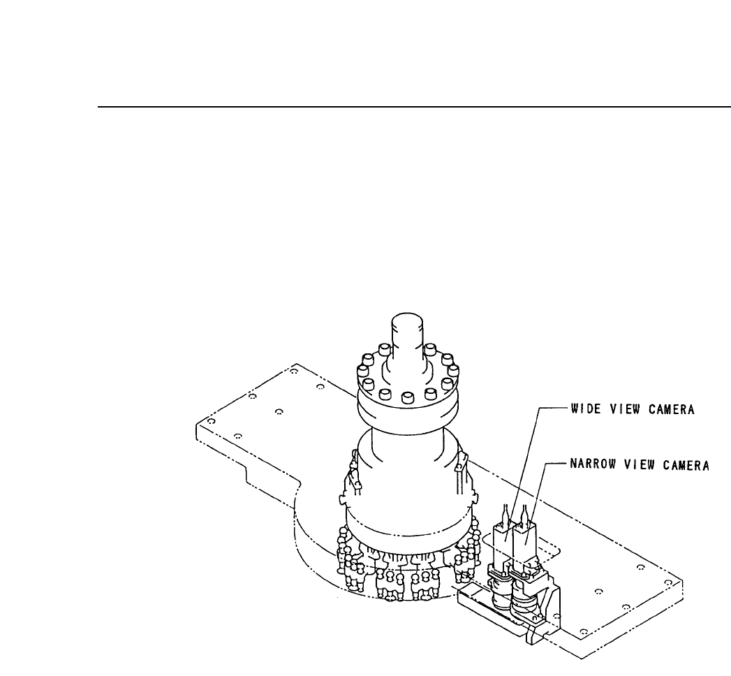
2. Two Camera System
Because some parts require highly accurate placing, the vision processing
system uses two cameras: a wide view and a narrow view camera.
2.1 System Configuration
The cameras are mounted as shown below.
2.2 Wide View Camera and Narrow View Camera
2.2.1 Wide View camera
The wide view camera has a field of view as described below.
• Using a backlight, the camera can handle a part with a surface
of up to 16.5 square millimeters and dimensions of up to 12.5 X
20 mm.
• Using a frontlight, the camera can handle a part with a surface
of up to 20 square millimeters.
Generally speaking, the wide view camera can handle parts
between size 1608 and SQFP 48 pin. It can also handle parts
smaller than 1608 but with reduced placing accuracy.
2 – 24Version 2.0
FCP IV-3 Operation