CP43操作手册.pdf.pdf - 第93页
Chapter 2 T wo Camera System Part 2 2.2.2 Narrow V iew Camera The field of view for the narrow view camera is up to 9 squar e millimeters. This camera can handle parts as small as size 1005. The narrow view camera takes …
Chapter 1 Automatic OperationPart 2
2. Two Camera System
Because some parts require highly accurate placing, the vision processing
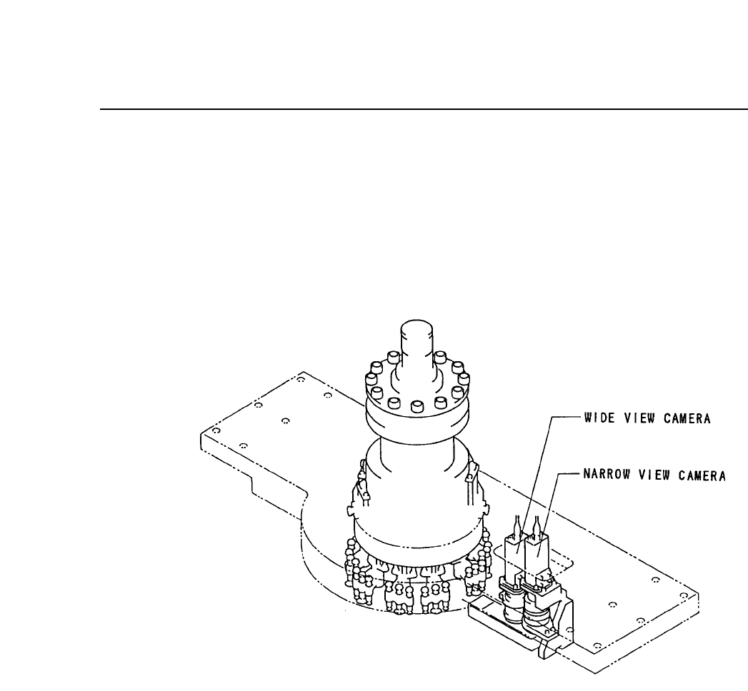
system uses two cameras: a wide view and a narrow view camera.
2.1 System Configuration
The cameras are mounted as shown below.
2.2 Wide View Camera and Narrow View Camera
2.2.1 Wide View camera
The wide view camera has a field of view as described below.
• Using a backlight, the camera can handle a part with a surface
of up to 16.5 square millimeters and dimensions of up to 12.5 X
20 mm.
• Using a frontlight, the camera can handle a part with a surface
of up to 20 square millimeters.
Generally speaking, the wide view camera can handle parts
between size 1608 and SQFP 48 pin. It can also handle parts
smaller than 1608 but with reduced placing accuracy.
2 – 24Version 2.0
FCP IV-3 Operation

Chapter 2 Two Camera SystemPart 2
2.2.2 Narrow View Camera
The field of view for the narrow view camera is up to 9 square
millimeters.
This camera can handle parts as small as size 1005.
The narrow view camera takes a small part and magnifies the
picture so that high accuracy placement can be carried out.
The narrow view camera can handle large parts, but since it
computes highly accurate placing coordinates vision processing on
large parts takes a long time.
2.3 Data Necessary to Use the 2 Camera System
To make use of the 2 camera system, the following data must be entered
into Proper and Part data.
2.3.1 Necessary Proper Data
125.Narrow Camera Use
For machines which come equipped with a narrow view camera
this is always set to "Use". It is not necessary for the user to make
this setting.
2.3.2 Necessary Part Data
12.Camera_type Wide Narrow
When using the wide camera for vision processing, set this entry in
vision data to "Wide;" and when using the narrow camera set it to
"Narrow."
2 – 25Version 2.0
FCP IV-3 Operation

Chapter 2 Two Camera SystemPart 2
3. Block Skip
A single board can be divided into many smaller boards or blocks. This is
called a multi-block board. On multi-block boards there may be cases when not
all blocks are free of defects. If there is a defective block on the board, this
block can be skipped by using the block skip function while the remaining
blocks continue to be produced.
How to use this function on the FCP IV-3 is explained in this chapter.
3.1 Block Skip Method
The three methods of setting the block skip function are described below.
• Using the Skip function in N_data of MCS/2H. This is effective for
skipping specific blocks in a large lot. For further information, refer to
the MCS/2H System Operation Manual.
• Using the [SKIP] command function on the machine. This is effective
for skipping specific blocks in a small lot. For further information
refer to Section 3.2.1.
• Using the machine fiducial camera to read block skip marks. This is
good for random block skips. For more information on reading block
skip marks with the fiducial camera, refer to Section 3.2.2 or to the
MCS/2H System Operation Manual.
3.2 Setting Block Skip
The block skip can be set at the operation panel on the machine. It can
also be set by programming a block skip mark on the appropriate part of
the board, which the camera will read to determine whether a block will
be skipped. Some simple examples are described below.
3.2.1 Using Machine Commands
(1) Using the MCS/2H Skip function in N_data, create a multi-
block program and transmit it to the FCP IV-3.
(2) Using the FCP IV-3 [PROGRAM] command (or with MCS/2H)
select the program transmitted in step (1) above.
(3) Press the [PROGRAM], [SKIP] and [BLOCK] command
function keys.
The display will change to the one shown on the next page. In
this display block 5 has been set to be skipped.
2 – 26Version 2.0
FCP IV-3 Operation