00196624-04_Service Manual WPC5_6_EN_01-2019.pdf - 第129页
Service Ma nual W PC5 / WPC6 ➢ Confirm the n ew position at which the limit switch triggers with (1). Calibrating the limit sw itch + ➢ Select the feed ax is (1). ➢ Select the func tion a nd continue with the same proced…
Service Manual WPC5 / WPC6
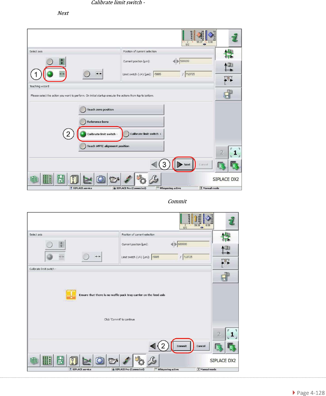
4.2.4 Calibrating the Limit Switch
The plus and minus position of the limit switches need to be calibrated.
Calibrating the limit switch -
➢ Select the feed axis (1).
➢ Select the function (2).
➢ Select (3).
➢ Follow the instruction shown and continue with (1).
Service Manual WPC5 / WPC6
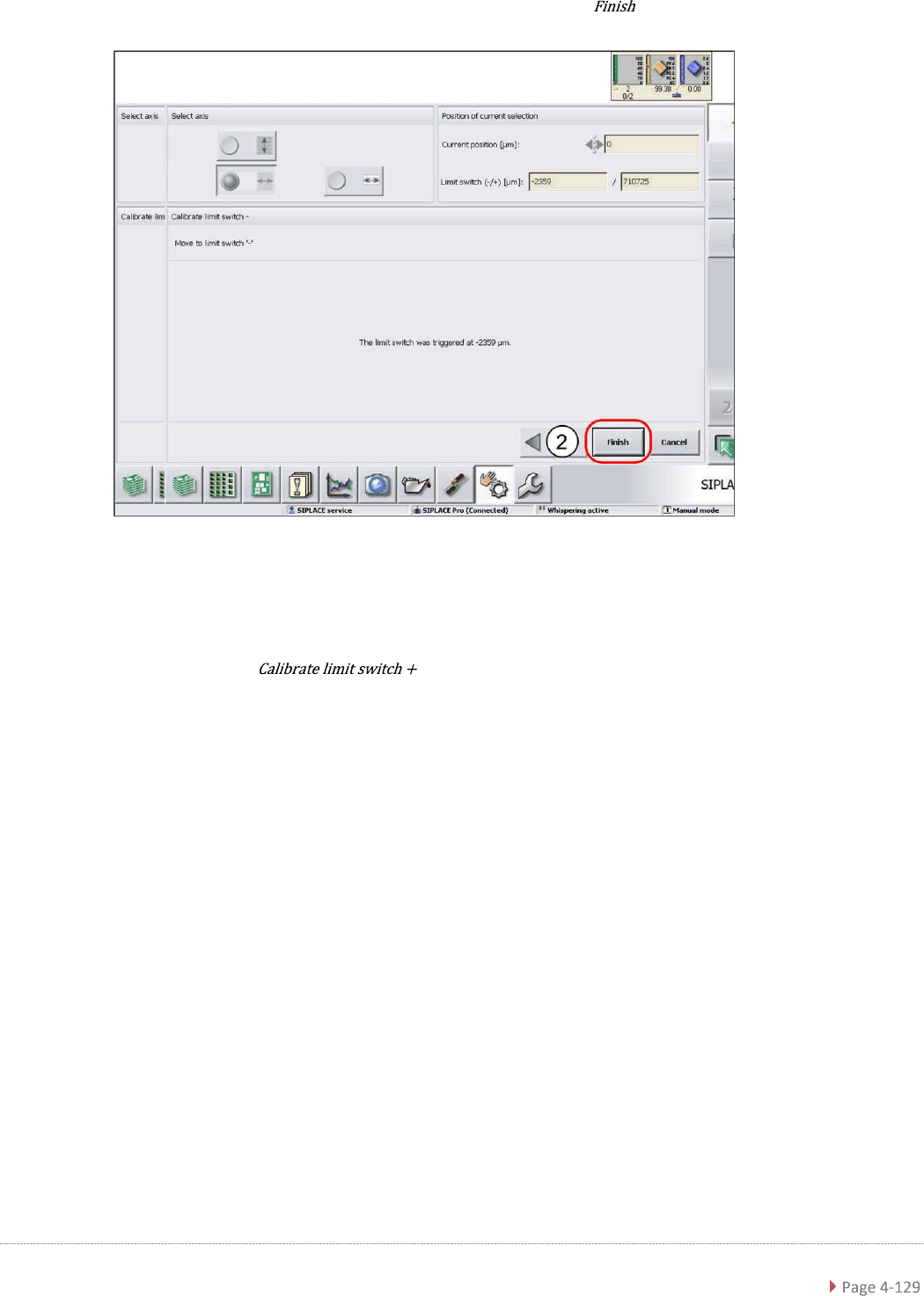
➢ Confirm the new position at which the limit switch triggers with (1).
Calibrating the limit switch +
➢ Select the feed axis (1).
➢ Select the function and continue with the same procedure as that
used for calibrating the limit switch.
Service Manual WPC5 / WPC6
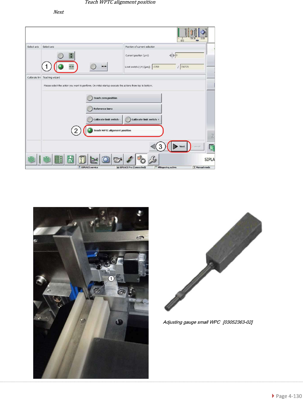
4.2.5 Teaching the WPTC Transfer Position
➢ Select the feed axis (1).
➢ Select the function (2).
➢ Select (3).
➢
Insert the calibration pin “Adjusting gauge small WPC” [03052363-02] on the front end of the
feed axis (1).
“ ”