00196624-04_Service Manual WPC5_6_EN_01-2019.pdf - 第136页
Service Ma nual W PC5 / WPC6 ➢ Confirm the n ew reference poi nt proximity switch with (1). Setting the Driver Ca m ➢ Loosen the screw (1), fasten ing the cam to the dr iver. ➢ Correct the p osition of the cam by mov ing…
Service Manual WPC5 / WPC6
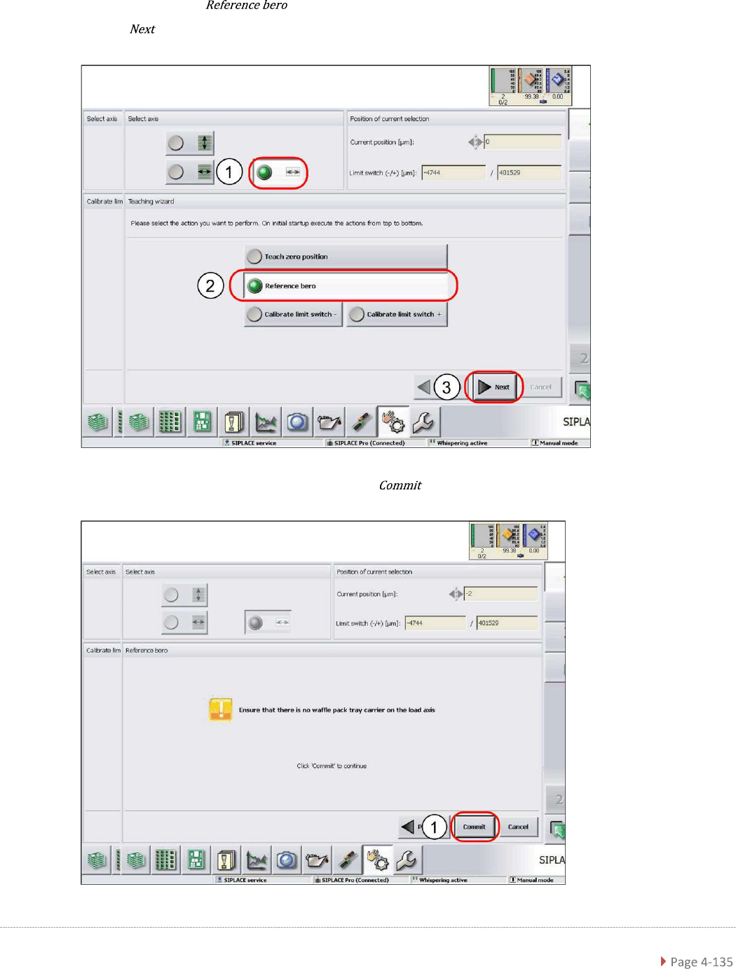
4.3.2 Reference Proximity Switch (Bero)
➢ Select the load axis (1).
➢ Select the function (2).
➢ Select (3).
➢ Follow the instruction shown and continue with (1).
Service Manual WPC5 / WPC6
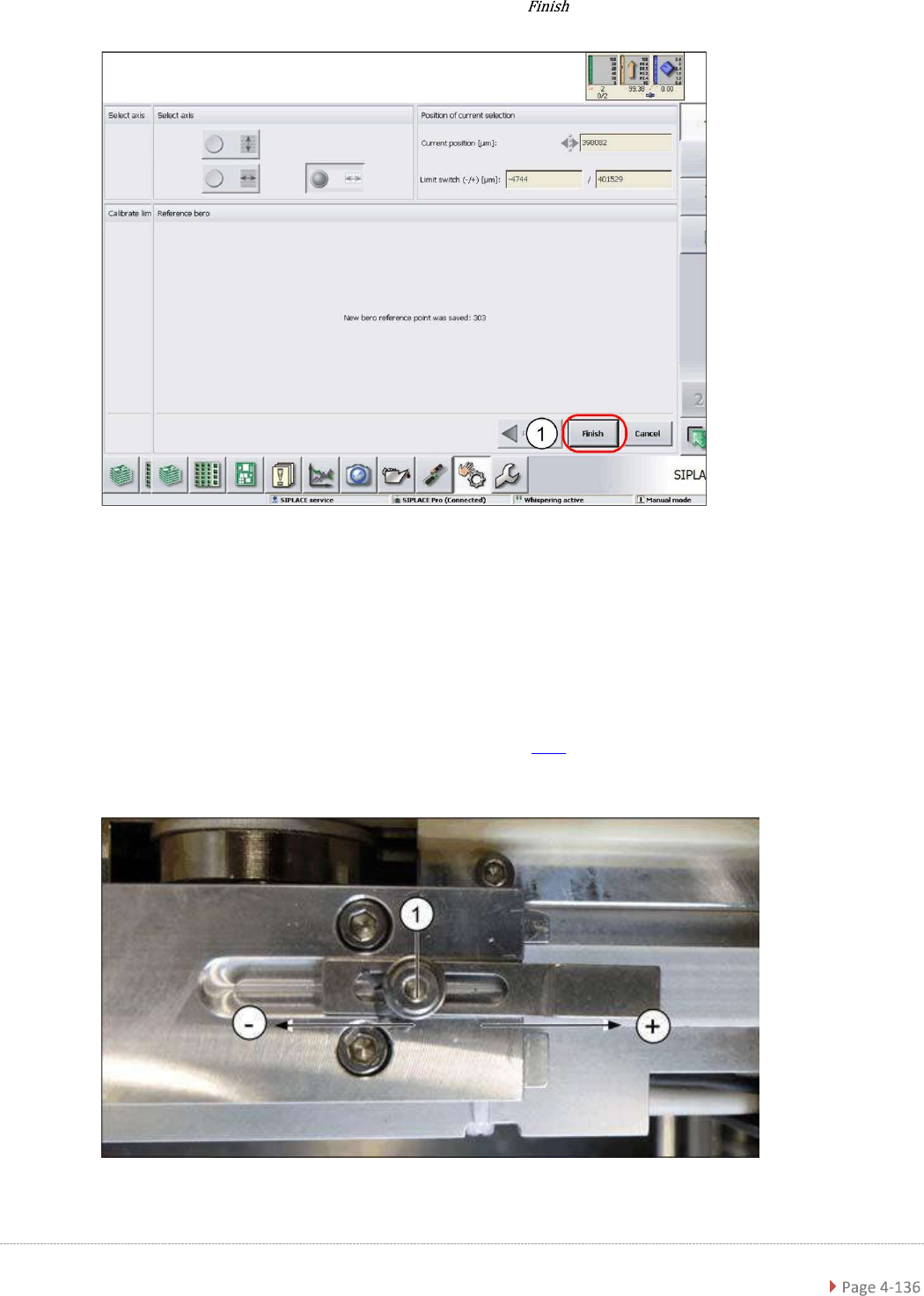
➢ Confirm the new reference point proximity switch with (1).
Setting the Driver Cam
➢ Loosen the screw (1), fastening the cam to the driver.
➢ Correct the position of the cam by moving it accordingly in either the – or + direction.
➢ Retighten the screw (1) and repeat the measuring steps (see "3.7.13 Replacing the
Reference Point.
Proximity Switch for the Load Axis [03056947-xx]" [➙ 3-99]).
➢ Wiederholen Sie die einzelnen Schritte, bis keine Fehlermeldung mehr erscheint.
Service Manual WPC5 / WPC6
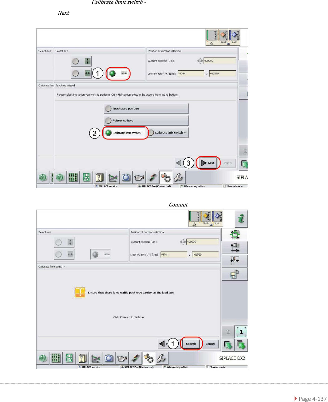
4.3.3 Calibrating the Limit Switch
The plus and minus position of the limit switches need to be calibrated.
Calibrating the limit switch -
➢ Select the load axis (1).
➢ Select the function (2).
➢ Select (3).
➢ Follow the instruction shown and continue with (1).