00196624-04_Service Manual WPC5_6_EN_01-2019.pdf - 第49页
Service Ma nual W PC5 / WPC6 ➢ Carefully insert the new contr oller board. ➢ Make sure t hat the contro ller board engages prope rly. ➢ Tighten the 4 screws fastening the front plate of the contr oller board. ➢ Lock the …
Service Manual WPC5 / WPC6
3.6.3.3 Replace the Controller Board
Spare Part
• WPC5 Controller Board [03057377-xx]
Removal / Installation
➢ Make a backup copy of the machine data, if this is still possible (*.xml). See "4.5 Storing and
Restoring Machine Data" [➙ 4-140].
➢ Wear the ESD wristband.
➢ Unplug the CAN bus cable from the front of the controller board.
➢ Loosen the 2 screws fastening the front plate of the controller board.
➢ Unlock the top and bottom locks.
➢ Carefully pull the controller board (see "3.6.3 Control Unit" [➙ 3-47]) out of the control unit.
➢
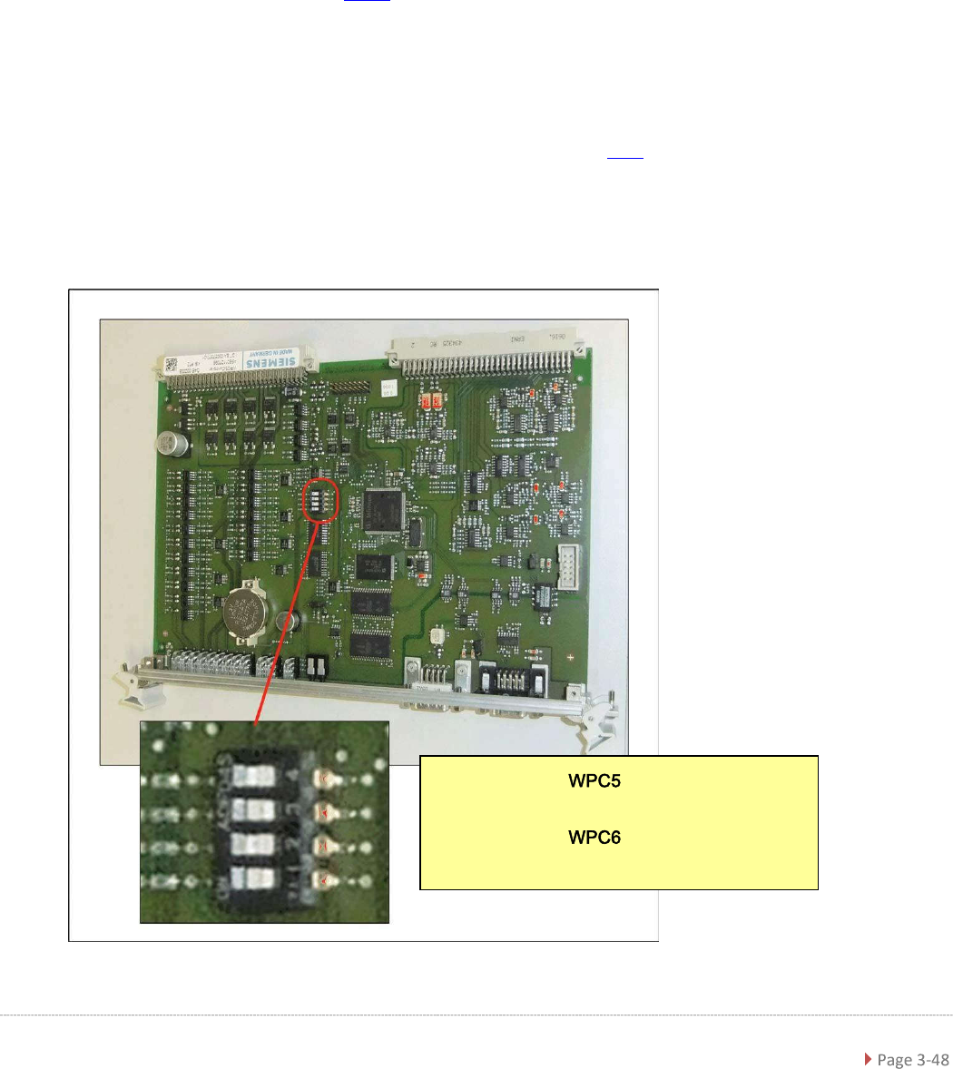
Make sure that the jumper on the new controller board is set identically to that on the
controller board to be replaced.
Position of the Jumper on the Controller
Board
•
Settings for :
Jumper 1 to 3 Off, Jumper 4 On
•
Settings for :
Jumper 1 and 3 Off, Jumper 2 and 4 On

Service Manual WPC5 / WPC6
➢ Carefully insert the new controller board.
➢ Make sure that the controller board engages properly.
➢ Tighten the 4 screws fastening the front plate of the controller board.
➢ Lock the top and bottom locks.
➢ Plug the CAN bus cable back into the front of the controller board..
Settings
➢ Restore the previously saved *.xml file. See section.
➢ For more information, refer to the Online Help for the station software. See "4.5 Storing and
Restoring Machine Data" [➙ 4-140].
NOTICE
Backup battery
A backup battery is located on the controller board..
Change the backup battery if the error message "17802 WPC: Voltage of back-up
battery is too low" is issued..
NOTICE
Calibration
If a current XML file can be backed up and restored, you do not need to recalibrate the
WPC.
However, if file restoration is not possible, you will need to recalibrate the WPC.
Service Manual WPC5 / WPC6
3.6.3.4 Replace the Axis card
Spare Part
• Axis KSP A364 analog [03041865-xx]
Removal / Installation
➢ Wear the ESD wristband.
➢ Loosen the 2 screws fastening the front plate of the axis card.
➢ Carefully pull the axis card (see "3.6.3 Control Unit" [➙ 3-47]) out of the control unit.
➢ Carefully insert the new axis card.
➢ Make sure that the axis card engages properly.
➢
Tighten the 2 screws fastening the front plate of the axis card.
Settings
➢ Perform a firmware download for the axis card..
➢ For more information, refer to the Online Help for the station software.