00196624-04_Service Manual WPC5_6_EN_01-2019.pdf - 第69页
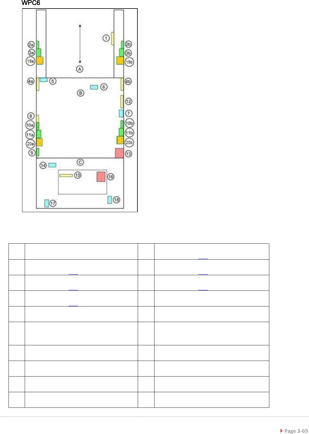
Service Ma nual W PC5 / WPC6 Schematic location and positi on - top view WPC6 A = Feed ax is; B = Tower (l ifting axis); C = Loadin g unit 1 sensor WPTC available [03056853-xx] 10a/ 10b crash lig ht barrier for high comp…
Service Manual WPC5 / WPC6
3.7 Limit Switches, Sensors and Light Barriers
3.7.1 Indroduction
3.7.1.1 Overview
WPC5
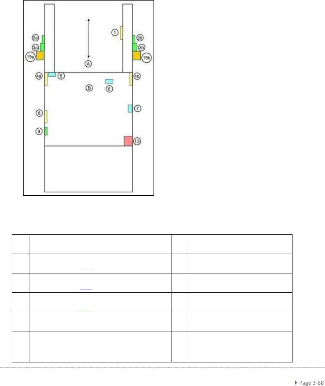
Schematic location and position - top view WPC5
A = Feed axis; B = Tower (lift axis)
1
sensor WPTC available [03056853-xx]
6
Reference sensor, lifting axis
[03047278-xx]
2a/
2b
crash light barrier for normal components
(see table on page 3-82)
7
Sensor "WPTC present in tower"
[03057841-xx]
3a/
3b
crash light barrier for high components
(see table on page 3-82)
8
Sensor "WPTC lock closed" [03056854-
xx]
19a/
19b
crash light barrier for very high components
(see table on page 3-82)
9
Reference sensor, feed axis [03057837-
xx]
4a/
4b
crash light barrier for feed axis, tower [03056927-xx] 13
Locking switch for door
5
Limit switch for lifting axis up [03047279-xx]/
limit switch for lifting axis down [03047280- -xx]
(fitted when lifting axis is down
Service Manual WPC5 / WPC6
Schematic location and position - top view WPC6
A = Feed axis; B = Tower (lifting axis); C = Loading unit
1 sensor WPTC available [03056853-xx]
10a/
10b
crash light barrier for high components, load axis
(see table on page 3-82)
2a/
2b
crash light barrier for normal components
(see table on page 3-82)
11a/
11b
crash light barrier for normal components, load axis
(see table on page 3-82)
3a/
3b
crash light barrier for high components
(see table on page 3-82)
20a/
20b
crash light barrier for high components NSM
(see table on page 3-82)
19a/
19b
crash light barrier for high components NSM
(see table on page 3-82)
12
Reference sensor, feed axis
[03057837-xx]
4a/
4b
crash light barrier for feed axis, tower
[03056927-xx]
13 Locking switch for door
5
Limit switch for lifting axis up [03047279-
xx] / limit switch for lifting axis down
[03047280-xx] (fitted when lifting axis is down
14
Sensor tray detection load axis
[03056989-xx]
6
Reference sensor, lifting axis
[03047278-xx]
15 Sensor safety flap open [03056958-xx]
7
Reference point proximity switch for load
axis [03056947-xx]
16 Safety sensor hand guard [03056990-xx]
8
Sensor "WPTC present in tower"
[03057841-xx]
17 Safety sensor loading flap [03056989-xx]
9 Sensor "WPTC lock closed" [03056854-xx] 18
Sensor tray correctly inserted
[03056959-xx]
Service Manual WPC5 / WPC6
3.7.1.2 General Installation/Removal Instructions
Tools and Equipment Required
• Standard tool
• Cable ties
• For a detailed overview of the connections, see "3.7.1.3 Detailed Connections for Limit
Switches, Sensors and Light Barriers" [
➙
3-71].
Cable routing
The cables are fixed and collected together with cable ties. Remove any cable ties which you do
not need with suitable wire cutters. Note how the cables are run and the position of the cable ties.
Fix new cable ties in the same positions as the old ones.
Some cables will be fixed with cable clamps which are held by a socket-head screw. Note how
the cables are run and fit the cable clamps with the socket-head screw in the same positions as
they were before.
CAUTION
Take care not to damage the cables!
Make sure that the cables do rub against any parts and that they are not pinched or damaged
when the lifting and feed axes move..
➢ Make sure that the cables are fixed with cable ties and/or clamps.
➢
Make sure that the cables do not rub against any parts and are not pinched when the lifting
and feed axes move.
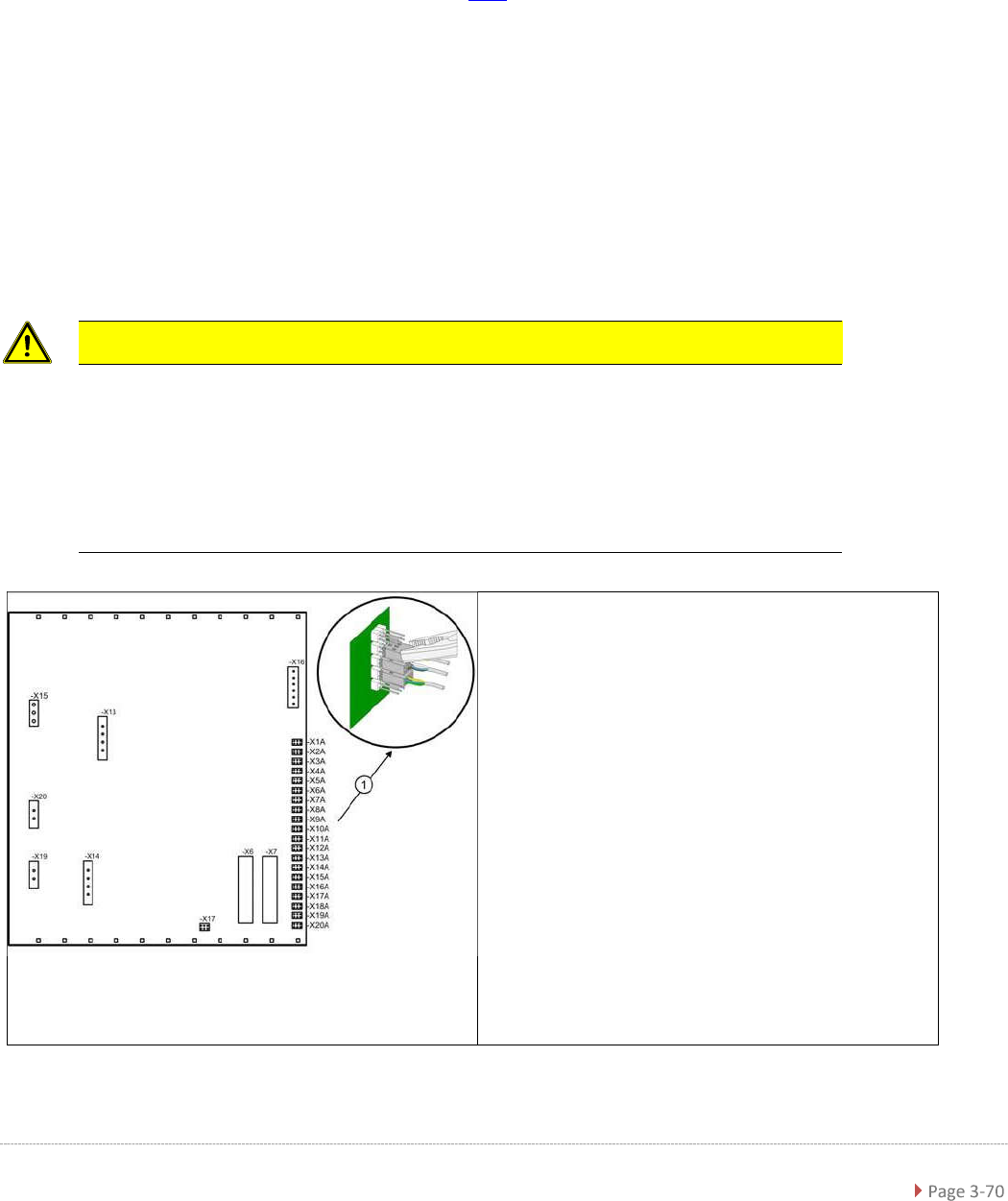
Note the terminal assignment
All sensor cables lead to the back plane of the
control unit and are connected to the right-hand
terminal strip there - X1a to X13a (1) .
➢ Check whether all cables are labeled.
➢ Make sure that you are able to correctly assign
all cables and plugs again. Where necessary,
label cables, plugs and connections for easier
reconnection later.
➢ Carefully disconnect the required connections
from the relevant terminal (1) with a suitable
pair of pliers (e.g. combination pliers). Make
sure that you do not bend the contact pins.