00196624-04_Service Manual WPC5_6_EN_01-2019.pdf - 第94页
Service Ma nual W PC5 / WPC6 3.7.9 Sensor 5 Top Lifting axis limited switch Spare Part • Top lifting axis limit switch [03047279 -01] Removal / Install ation ➢ Mark the exa ct position of the limit sw itch. ➢ Loosen the …
Service Manual WPC5 / WPC6
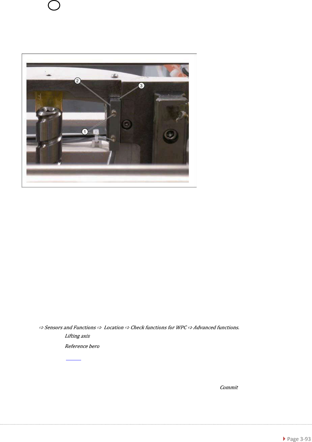
3.7.8 Sensor 6 Reference Sensor "Lifting axis“
Spare Part
• Reference point proximity switch for lifting axis [03047278-01]
Removal / Installation
➢ Loosen the two fastening screws (1) on the reference sensor.
➢ Loosen the cable clamps and remove the cable ties.
➢ Unthread the connection cable as far as the control unit back plane and unplug it from the
terminal strip.
➢ Fit the reference sensor so that the sensor surface (2) points to the side.
➢ Align the reference sensor parallel to the right-hand and top stopper edges (3).
➢ Restore the electrical connection and fix the connection cable into place.
Settings
➢ Check the function and correct position of the reference sensor.
➢ To do this, open the following function in the main view:
➢ Select the button in the Axis entry field.
➢ Select the button in the entry field (see "4.2.3 Reference Proximity Switch
(Bero)" [➙ 4-126]).
⇨ The lifting axis is moved, approaches the reference sensor and determines the reference
point.
⇨ The calculated value will be shown and can then be saved with the button.
➢ If an error message appears, If necessary, correct the mechanical position of the limit switch
with the help of the slot (2) and repeat the measurement procedure.
Service Manual WPC5 / WPC6
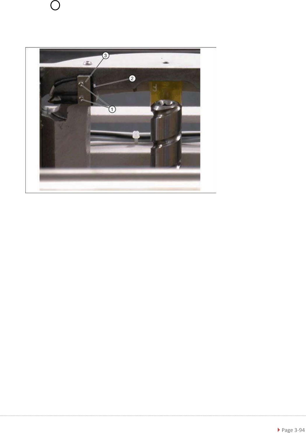
3.7.9 Sensor 5 Top Lifting axis limited switch
Spare Part
• Top lifting axis limit switch [03047279-01]
Removal / Installation
➢ Mark the exact position of the limit switch.
➢ Loosen the two fastening screws (1) on the limit switch.
➢ Remove the fixture plate (3).
➢ Loosen the cable clamps and remove the cable ties.
➢ Unthread the connection cable as far as the control unit back plane and unplug it from the
terminal strip.
➢ Fit the new limit switch.
➢ Fit the new limit switch with fixture plate (3) at the marked installation position.
➢ Restore the electrical connection and fix the connection cable into place.
Service Manual WPC5 / WPC6
Settings
➢ Check the function and correct position of the limit switch. The limit switch must switch when
the lifting axis moves over the switch (end position).
➢ To do this, open the following function in the main view:
.
➢ Select the radio button in the Axis entry field.
➢ Select the - button in the input area. (see also "4.1.4 Calibrating the Limit Switch"
[➙ 4-119]).
⇨ The lifting axis will be moved so that an actuator on the lifting axis moves over the limit
switch. The limit (end position) will be calculated.
⇨ Go to the main view and open the menu function
. Make sure that the view option is enabled.
⇨ A dialog box will open and the calculated value will be shown. The permissible limits
(minimum/maximum position) will also be shown. The end position must be within these
limits.
➢ Check the permissible limits against the value actually measured.
➢ If necessary, correct the mechanical position of the limit switch and repeat the measurement
procedure.
➢ If the value is within the permissible limits, save the data by clicking on
➢
Seal the two mounting bracket fastening screws with locking varnish.