TM-300_0wners_Manual.pdf - 第11页
TM-300 Ope ration Ins truct ion s 61170613. fm Page 5 of 27 Chapter 2 TM-300 Ope ration Instr uct ions This chapte r de scribe s the pro cedu res y ou mu st fol low to operate t he TM-3 00. Read all ins truc- tion s bef …
TM-300 Safety Instructions 61170511.fm Page 4 of 27
Customers who intend to service and maintain
the TM-300 themselves must have only quali-
fied personnel perform those procedures.
Qualified personnel are considered to be
those persons who have the proper technical
training, have experience to work on this
equipment, and are aware of the hazards to
which they will be exposed. The TM-300 pan-
els should never be removed with power
applied to the unit. Refer to the Operator
Manual for instructions before changing
Power Switch settings, changing fuses, or
removing any panels.
Caution should be taken when removing the
sealer from the TM-300. The body of the
sealer can maintain a high temperature long
after shut down. Procedure for removing the
Sealer is as follows:
Turn the POWER switch to the OFF position.
Shut off the air supply to the TM-300.
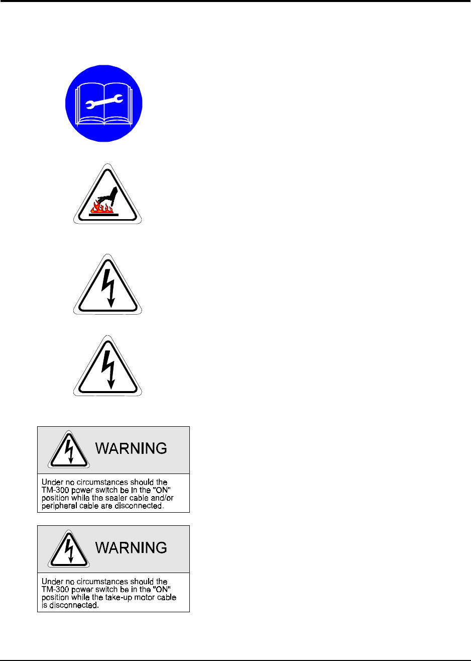
Dangerous voltage is present. Before servic-
ing:
Turn the POWER switch to the OFF position.
Shut off the air supply to the TM-300.
Disconnect the incoming power cord to the
TM-300.
Dangerous voltage is present. Follow the pro-
cedure below before removing this cover for
service or maintenance:
Turn the POWER switch to the OFF position.
Disconnect the incoming power cord to the
TM-300.
TM-300 Safety Instructions

TM-300 Operation Instructions 61170613.fm Page 5 of 27
Chapter 2
TM-300 Operation Instructions
This chapter describes the procedures you must follow to operate the TM-300. Read all instruc-
tions before operating the TM-300 and keep for future reference.
Chapter 2
Contents
Assembling Procedure........................................6
Completed Mechanical Assembly.......................8
Description..........................................................9
Counter Controls.................................................14
Setting the Counter.............................................15
Controller Operation............................................16
Software Download Procedure...........................17
Setup...................................................................19
Operation ............................................................25
Maintenance .......................................................27

TM-300 Operation Instructions 61170613.fm Page 6 of 27
Cover Tape Guide #1 (Ref. E)
Loosen the screw holding the tape guide (5/
32” allen wrench) and position at a 45° angle.
Tighten screw.
Feed Reel Support Arm (Ref. F)
Remove the black knob from the loading track
support arm (right side). Slide the feed reel
support arm onto the threaded rod, position it
at about 45°, and secure with the black knob.
Control Module Base Plate (Ref. G)
Slide the base plate into the control module
pedestal (Ref. K).
Control Module (Ref. H)
Place the control module on the control mod-
ule base plate. Connect all cables to the
matching connectors. (See External Connec-
tions, Page 9-10).
Assembling Procedure
Refer to Figure 2.1 for information below.
You will need:
1. 3/16” hex wrench
2. 5/32” hex wrench
3. 80 PSI air pressure system
Follower Track Support Arm (Ref. A)
Using the 3/16” hex wrench, attach the sup-
port arm to the base plate with the (5) bolts
provided.
Take-up Reel Drive Arm (Ref. B)
Remove the black knob from the follower track
support arm (Fig. 1, Ref. A). Slide the take-up
reel drive arm onto the threaded rod, position
it at about 45°, and secure with the black
knob.
Cover Tape Reel Support (Ref. C)
Using the 5/32” hex wrench, attach the cover
tape reel support to the seal assembly up-right
plate with the (2) bolts provided (See Fig. 2,
Ref. A). Remove the protective paper from
the cover tape front and rear covers (Ref. D)
and assemble as shown on page 3.