TM-300_0wners_Manual.pdf - 第12页
TM-300 Ope ration Ins truct ion s 61170613. fm Page 6 of 27 Co ve r T ape Guide #1 (Ref. E) Loo sen t he screw holdin g the tape guid e (5/ 32 ” al len wr ench) and pos i ti on at a 45 ° angle. Tighte n screw . Fee d Ree…

TM-300 Operation Instructions 61170613.fm Page 5 of 27
Chapter 2
TM-300 Operation Instructions
This chapter describes the procedures you must follow to operate the TM-300. Read all instruc-
tions before operating the TM-300 and keep for future reference.
Chapter 2
Contents
Assembling Procedure........................................6
Completed Mechanical Assembly.......................8
Description..........................................................9
Counter Controls.................................................14
Setting the Counter.............................................15
Controller Operation............................................16
Software Download Procedure...........................17
Setup...................................................................19
Operation ............................................................25
Maintenance .......................................................27

TM-300 Operation Instructions 61170613.fm Page 6 of 27
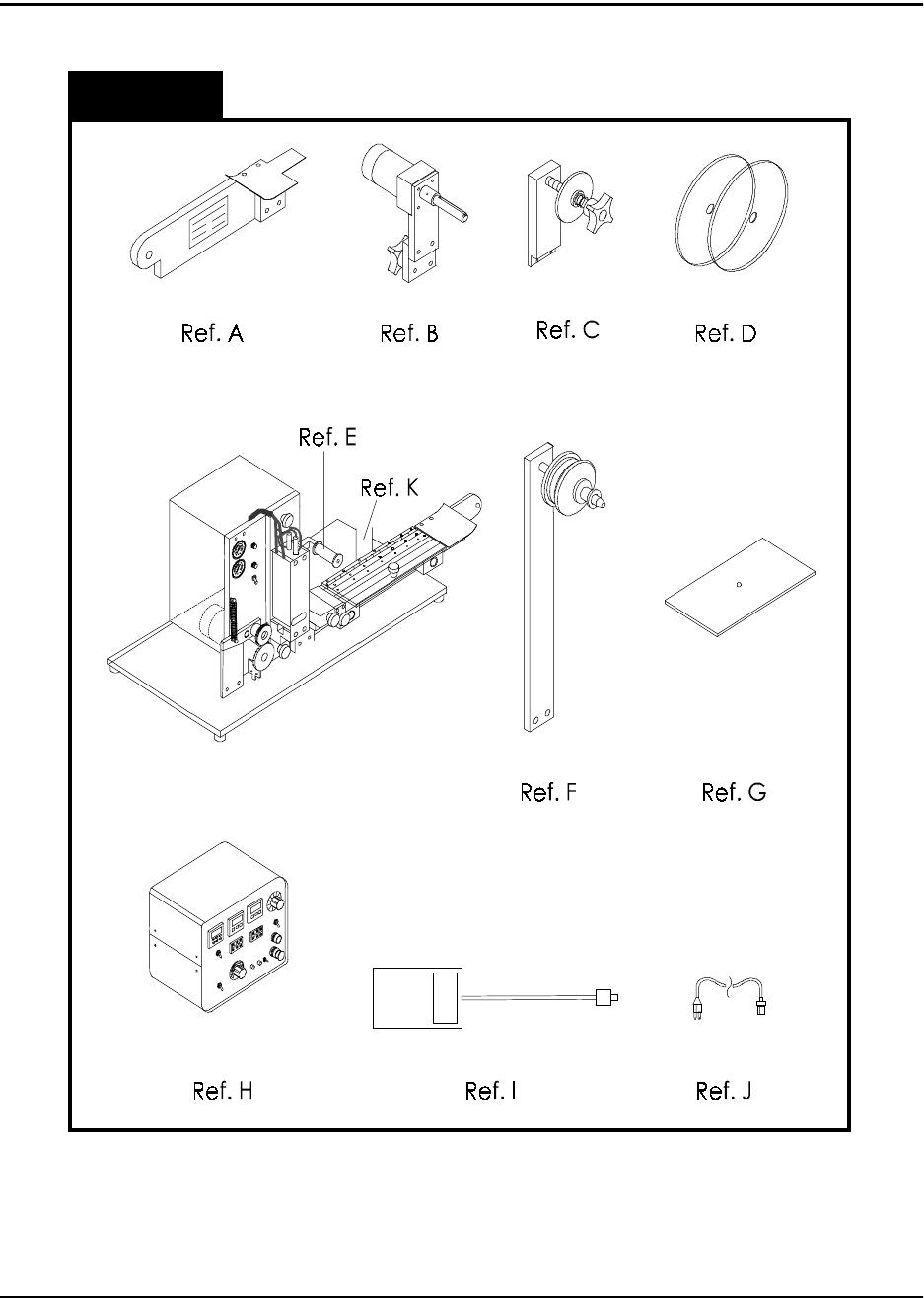
Cover Tape Guide #1 (Ref. E)
Loosen the screw holding the tape guide (5/
32” allen wrench) and position at a 45° angle.
Tighten screw.
Feed Reel Support Arm (Ref. F)
Remove the black knob from the loading track
support arm (right side). Slide the feed reel
support arm onto the threaded rod, position it
at about 45°, and secure with the black knob.
Control Module Base Plate (Ref. G)
Slide the base plate into the control module
pedestal (Ref. K).
Control Module (Ref. H)
Place the control module on the control mod-
ule base plate. Connect all cables to the
matching connectors. (See External Connec-
tions, Page 9-10).
Assembling Procedure
Refer to Figure 2.1 for information below.
You will need:
1. 3/16” hex wrench
2. 5/32” hex wrench
3. 80 PSI air pressure system
Follower Track Support Arm (Ref. A)
Using the 3/16” hex wrench, attach the sup-
port arm to the base plate with the (5) bolts
provided.
Take-up Reel Drive Arm (Ref. B)
Remove the black knob from the follower track
support arm (Fig. 1, Ref. A). Slide the take-up
reel drive arm onto the threaded rod, position
it at about 45°, and secure with the black
knob.
Cover Tape Reel Support (Ref. C)
Using the 5/32” hex wrench, attach the cover
tape reel support to the seal assembly up-right
plate with the (2) bolts provided (See Fig. 2,
Ref. A). Remove the protective paper from
the cover tape front and rear covers (Ref. D)
and assemble as shown on page 3.
TM-300 Operation Instructions 61170613.fm Page 7 of 27
Assembling Procedure
Figure 2.1