TM-300_0wners_Manual.pdf - 第16页
TM-300 Ope ration Ins truct ion s 61170613. fm Page 10 of 27 Description - Mec hanical Assembly Co ve r T ape Guide #3 (Ref. R) Adjustab le guide for p recisely po sitio ning the cove r ta pe ove r th e c arr ier tape pr…

TM-300 Operation Instructions 61170613.fm Page 9 of 27
Refer to Figure 2.2 for information below.
Cover Tape Reel Spindle (Ref. A)
Holds the bulk reel of cover tape and provides
appropriate tension to the cover tape.
Seal Pressure Gauges (Ref. B)
Monitor the pressure applied to the heat
shoes during the sealing process.
Seal Pressure Adjust Controls (Ref. C)
Set the amount of pressure applied to the heat
shoes during the sealing process.
Air Pressure ON/OFF Switch (Ref. D)
Turns the air pressure to the sealer on or off.
Idler Wheel (Ref. E)
Holds the carrier tape firmly to the drive
sprocket.
Drive Sprocket (Ref. F)
Powered by the drive motor, the drive sprocket
pulls the carrier tape through the TM-300 by
engaging the sprocket holes in the tape.
Take-up Reel Drive Motor (Ref. G)
Applies tension to the filled carrier tape as the
tape is wound on the take-up reel.
Take-up Reel Spindle (Ref. H)
Holds the take-up reel and applies tension to
wrap the filled carrier tape onto the take-up
reel.
Description - Mechanical Assembly
Tape Guide #3 (Ref. I)
Guides the filled carrier tape to the take-up
reel.
Pitch Setting Guide (Ref. J)
Guide used in finding the correct pitch of the
carrier tape. Used for setting the prescale on
the counter module.
Carrier Tape Quick Lock (Ref. K)
Holds the reel of carrier tape on the spindle.
Cover Tape Guide #1 (Ref. L)
Supports and guides the cover tape.
Carrier Tape Guide #1 (Ref. M)
Guides the bulk carrier tape into the loading
track.
Cover Tape Guide #2 (Ref. N)
Helps guide the cover tape into the sealing
mechanism.
Adjustable Loading Track (Ref. O)
Area where parts are placed in the carrier
tape. The outside edge of the track can be
moved to preset positions which will accom-
modate most tape widths.
Parts Cover (Ref. P)
Removable, see-through cover which allows
the operator access to parts which have been
placed in the carrier tape.
Carrier Tape Guide #2 (Ref. Q)
Guides filled carrier tape to heat shoes.

TM-300 Operation Instructions 61170613.fm Page 10 of 27
Description - Mechanical Assembly
Cover Tape Guide #3 (Ref. R)
Adjustable guide for precisely positioning the
cover tape over the carrier tape prior
to sealing.
Heat Sealer Assembly (Ref. S)
Controls the heat shoes with three variables:
time, temperature, and pressure. The assem-
bly is interchangeable for different tape widths.
Count Sensor (Ref. T)
Optical sensor which provides count pulses for
the counter module.
Drive Motor (Ref. U)
AC motor which powers the drive sprocket.
Idler Arm (Ref. V)
Holds the sealed tape against the drive
sprocket.
Seal Assembly / Motor Upright Plate
(Ref. W)
Supports the air pressure gauges, seal
assembly, and drive motors.
Follower Track Support Arm (Ref. X)
Supports the follower track, carrier tape guide
#3, and take-up reel drive arm.
TM-300 Operation Instructions 61170613.fm Page 11 of 27
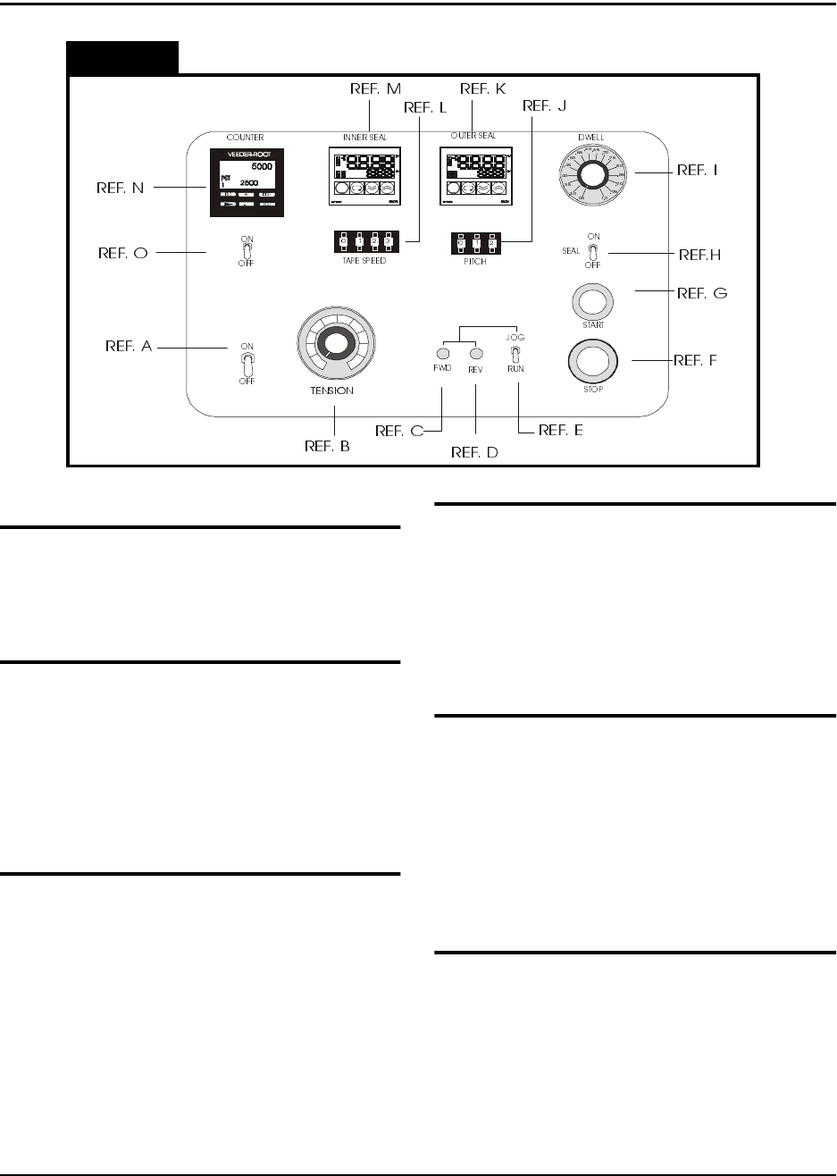
Decsription - Operating Controls
Figure 2.3
(Front Panel)
Power Switch (Ref. A)
The main power switch for the TM-300 Con-
troller provides power to the counter, take-up
motor, sealer and drive motor.
Tension Adjust (Take-up Motor) (Ref. B)
Adjusts the torque applied to the filled tape as
it is wrapped onto the take-up reel. Apply only
as much tension as needed to wrap the tape
onto the reel. Adjustments may need to be
made due to differing sizes and weights of
taped components.
FWD Button (Ref. C)
This button is used to advance the drive
sprocket by small increments for the purpose
of tape positioning. The JOG/RUN switch
must be set to JOG to use this feature.
REV Button (Ref. D)
This button performs the same function as the
FWD button, but in the reverse direction.
Extreme care must be taken if reverse posi-
tioning is to be performed since both the car-
rier and cover tape can jam when moving back
into the loading track.
JOG/RUN Switch (Ref. E)
When this switch is set to JOG, the TM-300
Controller is in the Tape Adjust mode, where
forward and backward positioning of the tape
is allowed.
When this switch is set to RUN, the TM-300
Controller is operating in normal taping mode.
Stop Button (Ref. F)
Pressing this button causes the motor to
immediately stop its motion and halts the pro-
gram at the current line number. Pressing the
START button allows the program to finish the
interrupted move.