TM-300_0wners_Manual.pdf - 第19页
TM-300 Ope ration Ins truct ion s 61170613. fm Page 13 of 27 Description - Opera ting Contro ls (cont.) F igure 2. 4 (Re ar Pane l) Serial/P arallel S witch (R ef. A) When th is switch is set t o SERIAL, new soft- war e …

TM-300 Operation Instructions 61170613.fm Page 12 of 27
Description - Operating Controls (cont.)
Start Button (Ref. G)
This button starts execution from the current
program line number. Pressing the START
button after a RESET will start execution at
the first program line. Pressing the START
button after an Emergency Stop (
E-Stop
) will
start the program at the line where the E-Stop
was detected.
Seal (Ref. H)
When set to ON, the seal is enabled.
When set to OFF, the seal is disabled.
Dwell (Ref. I)
The dwell knob is used to set the amount of
time the heat seal shoes remain on the cover
tape. There are 16 Dwell settings ranging
from 0.25 to 1.00 seconds in 0.05 second
intervals.
Temperature Controls (Ref. K and M)
The temperature controls set the temperature
of the heat shoes to a level that will cause the
heat sensitive adhesive on the cover tape to
melt. There are two separate controls:
Inner Seal (Ref. M)
This is the seal head closest to the
sprocket side of the carrier tape.
Outer Seal (Ref. K)
This is the seal head closest to the out-
side edge of the carrier tape as viewed
facing the machine.
Pitch (Ref. J)
The PITCH control is used to set software
parameters which control the drive sprocket
motor and the counter. For the TM-300 Con-
troller, PITCH refers to the distance (mm)
between pocket centers in the carrier tape.
The current factory default settings allow the
following PITCH settings:
4mm, 8mm, 12mm, 16mm, 20mm,
24mm, and 32mm.
Tape Speed (Ref. L)
This set of 4 Thumbwheel switches is used to
determine tape velocity. Speeds are entered
in pps (pulses per second) units. A new
speed may be selected whenever motion is
not in progress.
(Note: Acceleration/deceleration, and ramp-
ing profiles can be changed via software by
downloading programs with these parameters
varied).
Counter (Ref. N)
The counter keeps an accurate count of the
number of parts taped. The counter will auto-
matically keep an accurate parts count for any
tape pitch (pocket width). For counter opera-
tion, refer to the SETTING COUNTER section
of this manual.
Count (Ref. O)
In the ON position, the counter is enabled.
In the OFF position, the counter is disabled.
To set the target temperature, simply use the
Increment and Decrement keys to adjust the
set point display (Ref. C).
TM-300 Operation Instructions 61170613.fm Page 13 of 27
Description - Operating Controls (cont.)
Figure 2.4
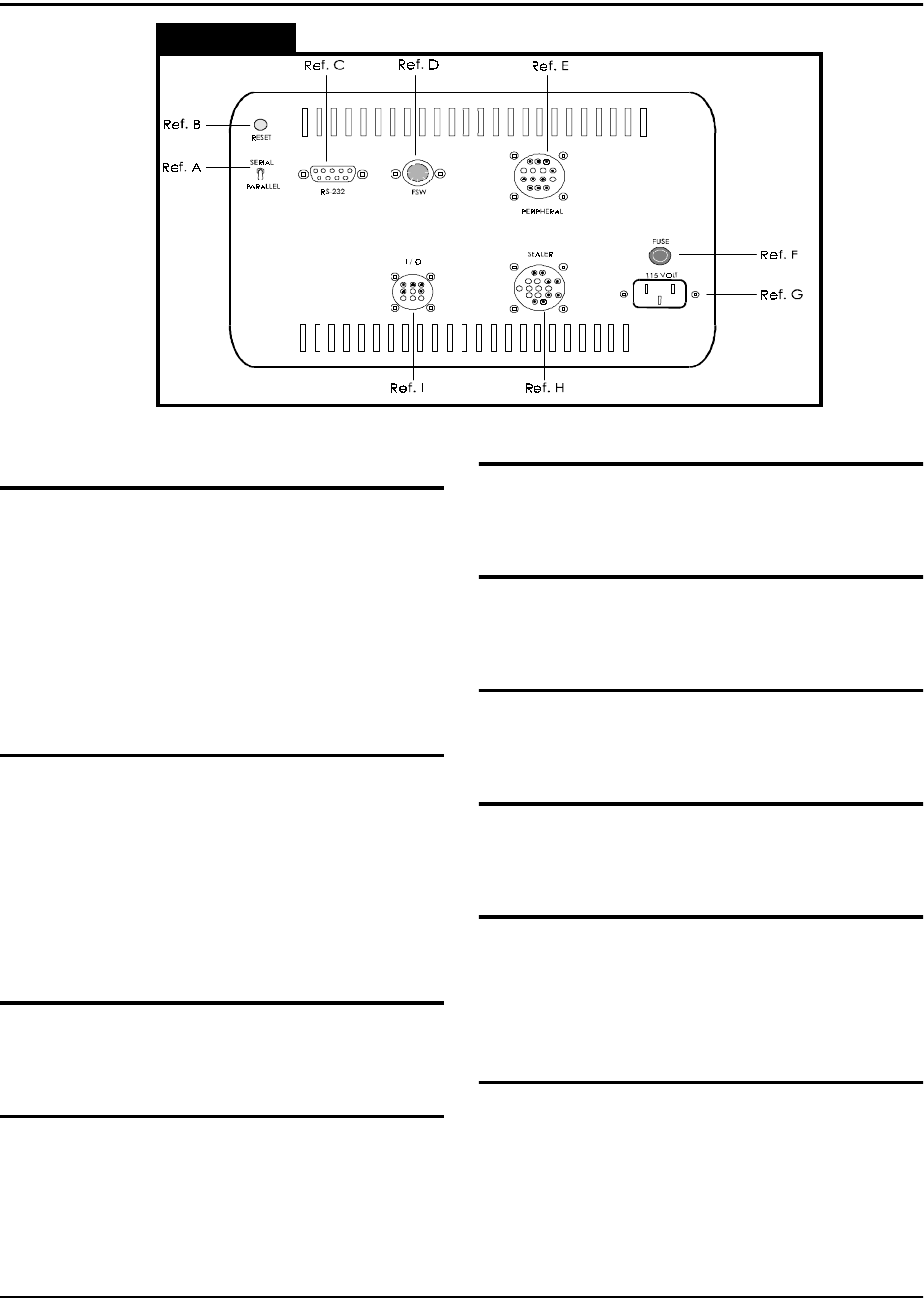
(Rear Panel)
Serial/Parallel Switch (Ref. A)
When this switch is set to SERIAL, new soft-
ware programs can be downloaded from a
personal computer (PC) to the TM-300 Con-
troller. For reliable operation, this switch
should be set to PARALLEL when operating in
normal RUN or STEP/JOG mode. When
downloading software, this switch must be set
to the SERIAL position.
Reset (Ref. B)
Pressing this button will stop current program
execution and reset the program line pointer
to the first line of the current program.
NOTE
:
The START button must be pressed to
restart program execution after Reset is acti-
vated.
RS-232 Conector (Ref. C)
This port allows communication between an
IBM compatible PC and the TM-300.
FSW (Ref. D)
This connector connects the footswitch to the
TM-300 controller.
Peripheral (Ref. E)
This connector provides connections from the
TM-300 Controller to motors on the machine.
Fuse (Ref. F)
The TM-300 uses a 1.5 Amp, 250 Volt, type
3AG fuse.
115VAC (AC Power Input) (Ref. G)
This is a 115VAC, 50-60 HZ input for AC
power.
Sealer (Ref. H)
Connects the heat seal assembly to the tem-
perature controllers.
I/O (Input/Output) (Ref. I)
This connector is reserved for future use. It
provides TWO logic level Inputs, one Motion
Busy Output, and a circuit Common, for future
hardware/software flexibility.
Air Regulator (Not Shown)
Connects the TM-300 to the air supply and
regulates the air pressure.
TM-300 Operation Instructions 61170613.fm Page 14 of 27
Counter Controls
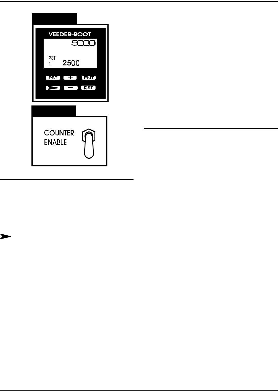
Figure 2.5
Figure 2.6
Counter Module (Figure 2.5)
PST-Preset Select
This key can be used to select data to be dis-
played when the PGM input is active, although
for normal operation of the TM-300 this key is
not used.
Next Digit
This key selects one digit of data to be
changed. The first keypress will select the
left-most digit; additional presses will select
digits further to the right. The chosen digit will
flash twice per second. That digit may then be
changed with the + and - keys
+/- Increment/Decrement
The (+) key will change the selected (flashing)
digit of Preset or Program Data by adding 1 to
it. Rollover occurs from 9 back to 0. The (-)
key similarily subtracts 1, and will roll under
from 0 to 9. Holding either key down will
cause the digit to change repeatedly about
twice per second.
RST (Reset)
The counter is reset to 0 when this key is
pressed.
ENT (Enter)
This key transfers edited Preset or Program
Data to nonvolatile memory. The newly
selected value is not used until the ENTER
key is pressed. During normal operation a ten
second timer is in effect. If a Preset has been
changed but not entered, the Preset Data will
revert back to its old value after ten seconds of
inactivity.
Count Enable Switch (Figure 2.6)
The Count Enable Switch has two positions:
up and down.
Up
In this position, the counter will be in its normal
operating mode. The count value will incre-
ment as the tape moves through the TM-300,
dependent on the setting of the Prescale value
(Pitch Setting).
Down
In this position, the counter will be disabled.
The TM-300 will function normally but the
count value will not increase.