TM-300_0wners_Manual.pdf - 第22页
TM-300 Ope ration Ins truct ion s 61170613. fm Page 16 of 27 Star tup Pr ocedur e T ur n the T M-300 C ont roller PO WE R switch t o ON. Pr ess the ST ART but to n to begi n p r o - gr am ex ec utio n. Run Mode Th e Run …
TM-300 Operation Instructions 61170613.fm Page 15 of 27
Setting the Counter
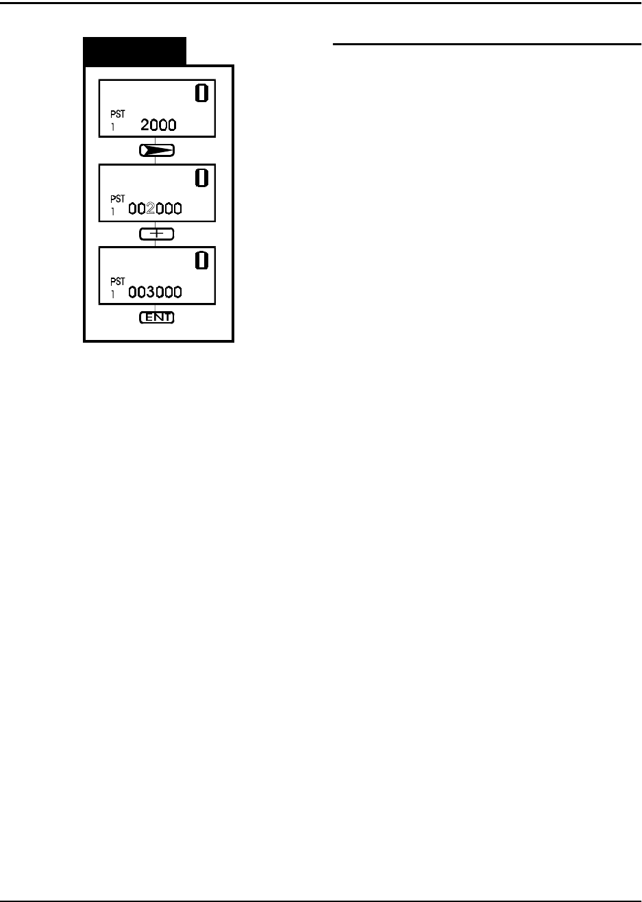
Figure 2.7
Changing the End Count Value
The Preset Data value is the end count, or tar-
get value, for the current job. The machine
will cease operation when the counter module
reaches this value. To continue tape move-
ment, press the RESET button on the counter
module.
This diagram shows the sequence for entering
new values in the Preset Data. This proce-
dure can be done with the Count Enable
Switch in either the UP or Down position.
Use the NEXT DIGIT key to select one digit to
change. The selected digit begins to flash.
Change the selected digit with the + and -
keys.
When all of the digits have been correctly set,
press the ENTER key to store the new value
in memory.
TM-300 Operation Instructions 61170613.fm Page 16 of 27
Startup Procedure
Turn the TM-300 Controller POWER switch to
ON. Press the START button to begin pro-
gram execution.
Run Mode
The Run Mode is the normal mode of opera-
tion for taping parts. In this mode the internal
software constantly monitors the PITCH,
TAPE SPEED, DWELL, and Emergency
STOP controls.
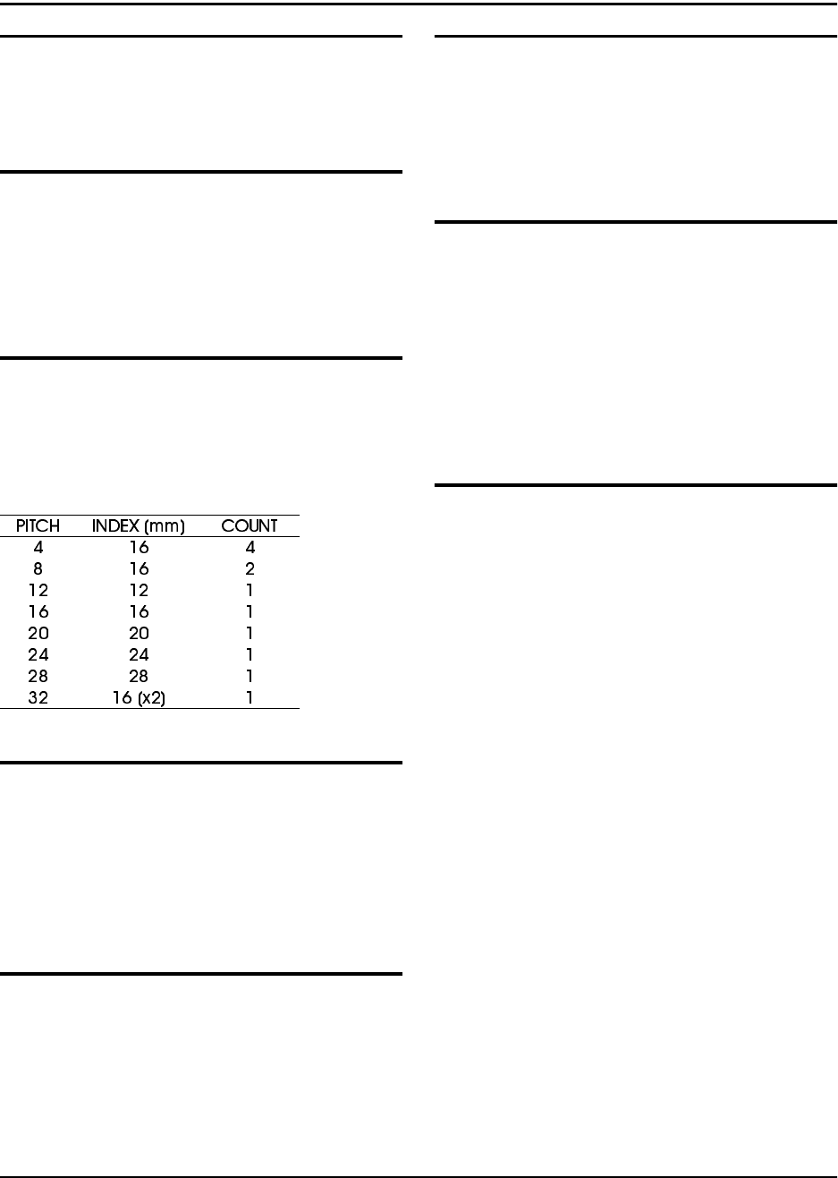
Pitch
For operation, it is essential that the PITCH
setting is correct for the type of carrier tape
used. The PITCH input allows the controlling
software to determine the correct carrier tape
movement and keep an accurate part count.
Tape Speed
Any time a motion begins, the controller reads
the TAPE SPEED inputs to determine the
velocity at which the carrier tape will travel.
Speed is entered in pps (pulses per second)
units. Any new TAPE SPEED setting will take
effect the next time a new motion is begun.
Dwell
After the carrier tape has advanced, the inter-
nal software reads the DWELL dial to deter-
mine how long the seal head should stay
down on the cover tape. Dwell times can be
selected from 0.25 to 1.00 second.
Controller Operation
Foot Switch (FSW)
Any time the FSW is momentarily pressed, the
TM-300 will advance the carrier tape, seal the
tape, and increment the counter. If the FSW is
pressed and held down, the previous cycle will
repeat until the FSW is deactivated.
Stop
If, for any reason, the operator needs to stop
any motion in progress, pressing the STOP
button will bring all motion to a controlled halt.
To continue a previously halted motion, press-
ing START will allow the motion to continue
from where it left off. Press the RESET button
followed by the START button to return to nor-
mal program mode.
Jog Mode (Tape Adjust)
In this mode, the operator may make fine
adjustments in the positioning of the carrier
tape. This feature is intended for initial posi-
tioning of the carrier tape before taping parts.
Fine positioning can be performed in either the
forward (FWD) or reverse (REV) directions.
FWD - Momentarily pressing the FWD button
advances the tape by 0.25mm. Pressing and
holding this button causes the tape to advance
4 times in 0.25mm increments, pause for one
second, and then jog continuously until the
button is released.
REV - Momentarily pressing the REV button
reverses the tape by 0.25mm. Pressing and
holding this button causes the tape to move
backwards in 0.25mm increments. Reverse
jogging is not allowed.
(Note: Care should be used when using the
REVERSE positioning button. The carrier/
cover tape may not freely feed back through
the sealer, cover tape guides, or loading track
mechanisms, causing a tape jam.)
TM-300 Operation Instructions 61170613.fm Page 17 of 27
Software Download Procedure
TM-300 Controller Setup
1. Disconnect the power cord from the back of
the machine.
2. Remove the cover on the controller to allow
for access to the components inside.
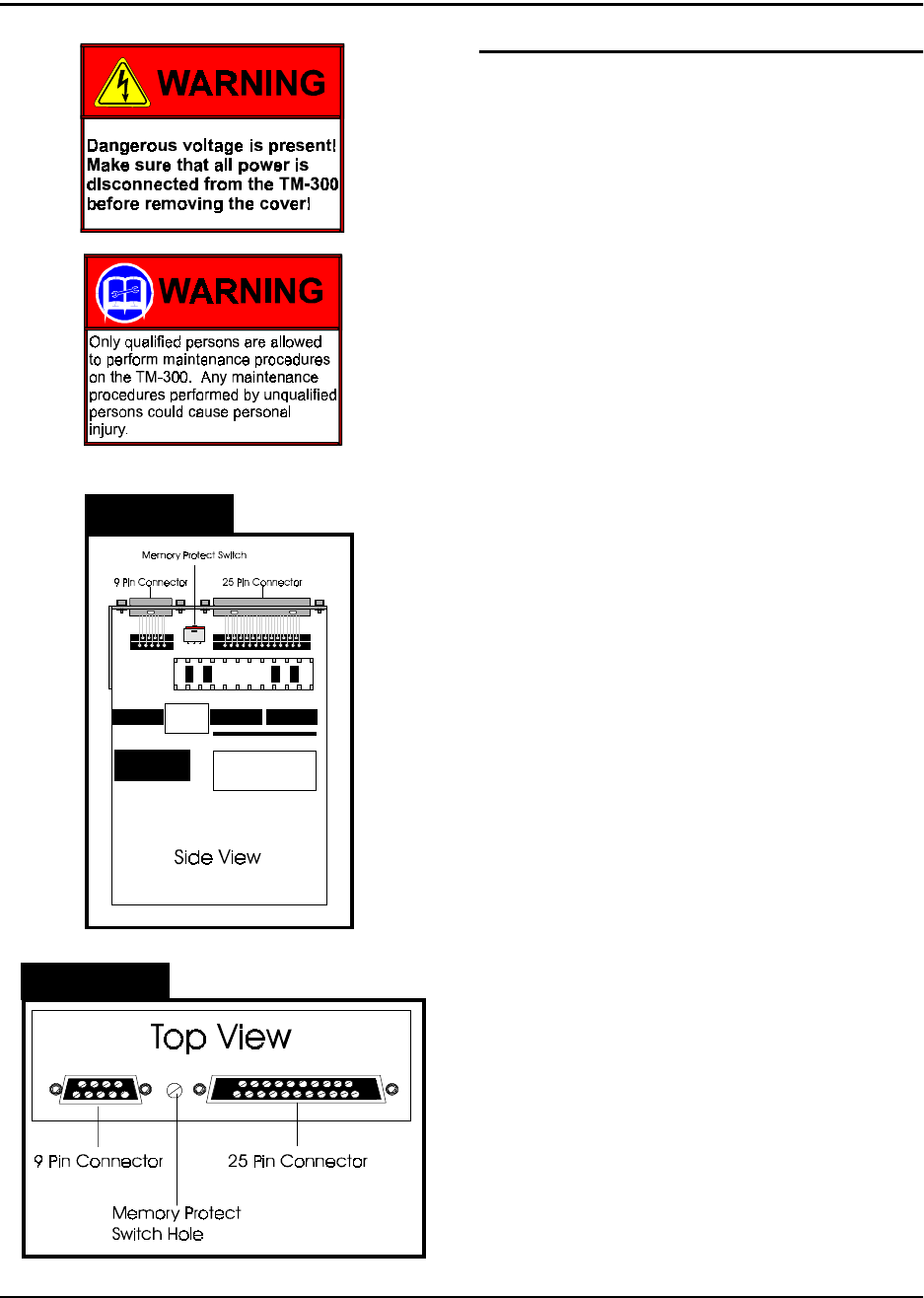
3. Locate the Slo-Syn Indexer Drive Module.
This module contains a memory protect switch
to help prevent accidental program and/or
parameter changes. When the switch is in the
PROTECT position changes can’t be made to
the program or the parameters. When the
switch is in the WRITE position, changes can
be made to the program or the parameters.
The memory protect switch is located between
the 9-pin and 25-pin connectors. When the
switch is positioned toward the 25-pin connec-
tor , the switch is in the WRITE position.
When the switch is positioned toward the 9-pin
connector the switch is in the PROTECT posi-
tion.
Set the switch in the WRITE position. This
can be done by using a small screwdriver to
either set the switch through the provided
hole, or by setting the switch on the board. If
setting the switch on the board, be careful not
to damage any components.
4. Connect the 9 pin 'D' male end of the com-
munications cable to the RS-232 port on the
rear panel of the TM-300 (Figure 4, Ref. C).
5. Verify that the TM-300 POWER switch is
ON.
6. Verify that the SERIAL/PARALLEL switch,
located on the rear panel, is set to the SERIAL
position.
7. Press the RESET button.
Figure 2.8
Figure 2.9