TM-300_0wners_Manual.pdf - 第24页
TM-300 Ope ration Ins truct ion s 61170613. fm Page 18 of 27 PC S etup 1. Connect the 9- pin 'D' fe mal e end of the comm unic at ions ca ble t o the COM1 port o n a PC (IB M co mpat ible persona l comp uter ).…
TM-300 Operation Instructions 61170613.fm Page 17 of 27
Software Download Procedure
TM-300 Controller Setup
1. Disconnect the power cord from the back of
the machine.
2. Remove the cover on the controller to allow
for access to the components inside.
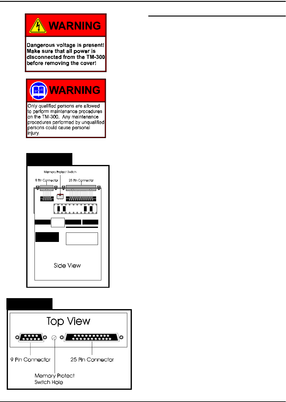
3. Locate the Slo-Syn Indexer Drive Module.
This module contains a memory protect switch
to help prevent accidental program and/or
parameter changes. When the switch is in the
PROTECT position changes can’t be made to
the program or the parameters. When the
switch is in the WRITE position, changes can
be made to the program or the parameters.
The memory protect switch is located between
the 9-pin and 25-pin connectors. When the
switch is positioned toward the 25-pin connec-
tor , the switch is in the WRITE position.
When the switch is positioned toward the 9-pin
connector the switch is in the PROTECT posi-
tion.
Set the switch in the WRITE position. This
can be done by using a small screwdriver to
either set the switch through the provided
hole, or by setting the switch on the board. If
setting the switch on the board, be careful not
to damage any components.
4. Connect the 9 pin 'D' male end of the com-
munications cable to the RS-232 port on the
rear panel of the TM-300 (Figure 4, Ref. C).
5. Verify that the TM-300 POWER switch is
ON.
6. Verify that the SERIAL/PARALLEL switch,
located on the rear panel, is set to the SERIAL
position.
7. Press the RESET button.
Figure 2.8
Figure 2.9

TM-300 Operation Instructions 61170613.fm Page 18 of 27
PC Setup
1. Connect the 9-pin 'D' female end of the
communications cable to the COM1 port on a
PC (IBM compatible personal computer).
2. Insert TM-300 SOFTWARE disk into PC.
3. Change directory to the drive containing
the DOWNLOAD disk.
Download Operation
1. Run the 'MS1.EXE' program on the TM-300
DOWNLOAD disk.
2. Select the 'UTILITY' pull down menu and
choose the 'DISK TO INDEXER' option.
3. At the "Program Name" prompt window,
type the <drive:> <filename.ext> of the pro-
gram to be downloaded.
(Example: 'A:TM300EXT.A01' )
4. At the "Indexer ID#" prompt window, verify
ID# <1>. Press ENTER and the PC terminal
will display the message ‘Transmitting File
<filename.ext> to Indexer’. The downloading
process takes approximately 20-30 seconds.
(Note: Do not press START or RESET while
download transmission is in progress, or the
download will be terminated and an error mes-
sage will occur).
5. If the error message (‘Indexer 1 did not
respond and is unable to accept program’)
appears on the screen, ensure that the SET-
UP conditions for both the TM-300 and PC are
correct and retry the downloading operation.
Software Download Procedure (cont.)
When Finished Downloading Program
1. Turn the main power OFF.
2. Once again, disconnect the power cord
from the back of the machine.
3. Place the memory protect switch in the
PROTECT position.
4. Remove the RS-232 Cable.
5. Replace the cover to the controller.
6. Set the SERIAL/PARALLEL switch to the
PARALLEL position so that the machine will
run.
7. Replace the power cord and turn the main
power ON.
8. Press the RESET and START buttons on
the controller to start the program.
Software Modification
The TM-300 Controller Software is factory set
with specific default values. However, some
applications may require special parameter
settings.
The following two (stepper motor) parameters
may be changed:
Ramping Profiles:
0- Trapezoidal
1- "S"
2- Hyperbolic
Acceleration/Deceleration constant
Additional software modifications may be
made for specific applications requiring fea-
tures not available in the current software for
the TM-300. Contact your V-TEK representa-
tive for more detailed information on making
software modifications.
TM-300 Operation Instructions 61170613.fm Page 19 of 27
Setup
Taping Assembly Setup
1. Mount Heat Sealer Assembly (Fig. 2.2,
Ref. T)
A sealer must be used which matches the
width of the carrier tape being used. To
remove an existing sealer, turn the sealer air
pressure switch OFF, disconnect the sealer
connector, and remove the two bolts which
secure the sealer to the up-right plate. Care-
fully lift the sealer away from the upright plate.
*CAUTION*-Sealers which have been in
use will be hot. Serious burns can result if
the heat shoes are touched.
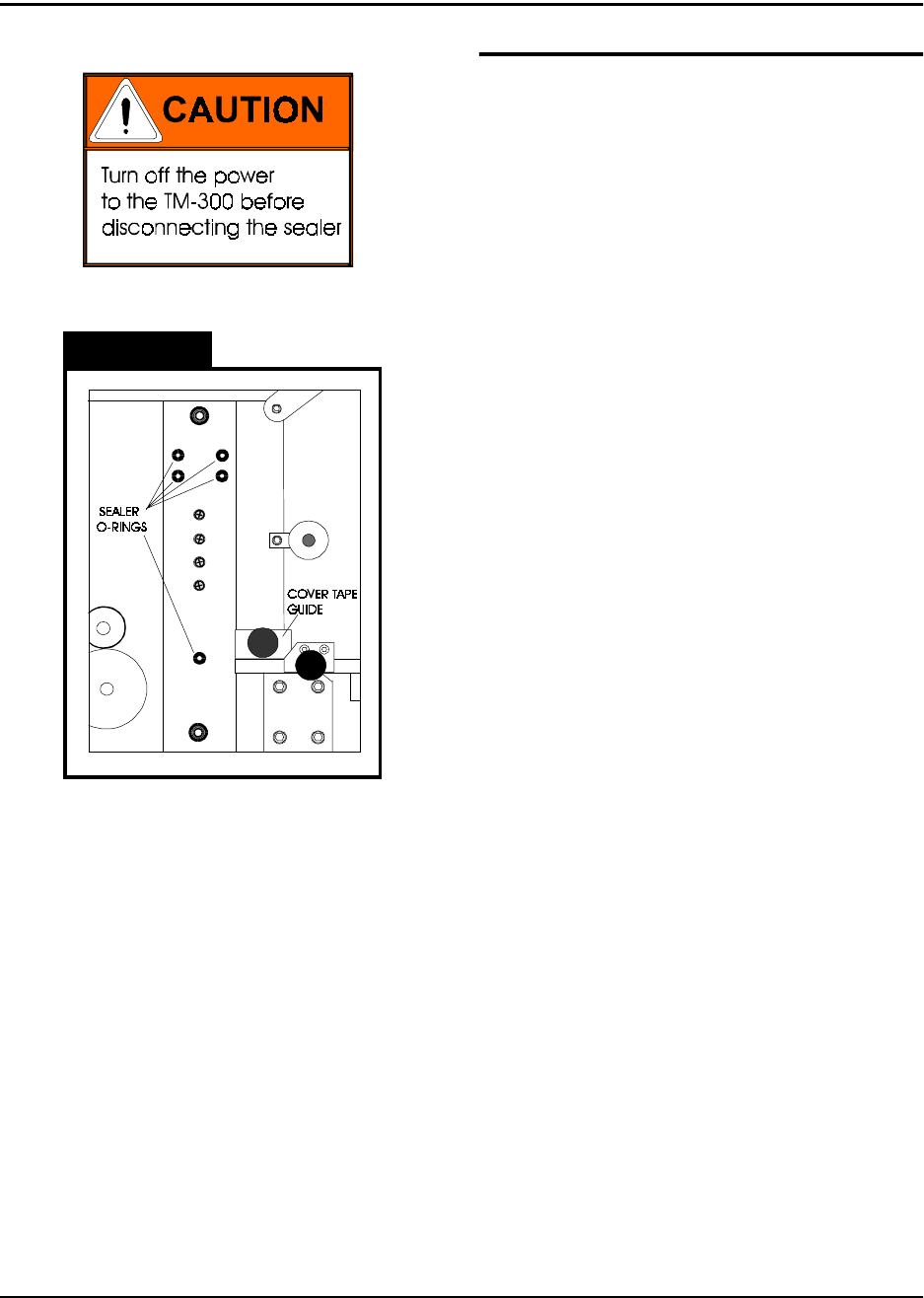
When mounting a new sealer, first inspect the
up-right plate where the sealer is mounted to
make sure all of the O-rings are in place.
There are (5) O-rings at the places shown
which must be in place for the sealer to func-
tion properly. Replace any missing or dam-
aged O-rings. A small amount of glue can be
used to secure the O-rings in their holes if they
are replaced.
Carefully lower the new sealer into position.
Do not hit the exposed corners of the loading
track with the sealer or they may be damaged.
Run the sealer connector and cord over the
top of the up-right plate and plug the connec-
tor into the receptacle on the back of the con-
troller. Secure the sealer with its two mounting
bolts.
There is a cover tape guide which accompa-
nies every sealer (Fig. 2.2, Ref. S). When
changing sealers, this guide must also be
changed. To do so, remove the knurled, metal
knob which secures it in place and slide the
guide straight off. Once the new sealer is in
place, mount the new cover tape guide, mak-
ing sure its marked tape width matches that of
the sealer.
Figure 2.10