TM-300_0wners_Manual.pdf - 第27页
TM-300 Ope ration Ins truct ion s 61170613. fm Page 21 of 27 Setup (con t.) 4. Load T apes into Sealer Pull the cover tape down through the cover ta pe gui des as sh own. Pu ll abou t 12 ” of cov er ta pe ou t an d l ay …
TM-300 Operation Instructions 61170613.fm Page 20 of 27
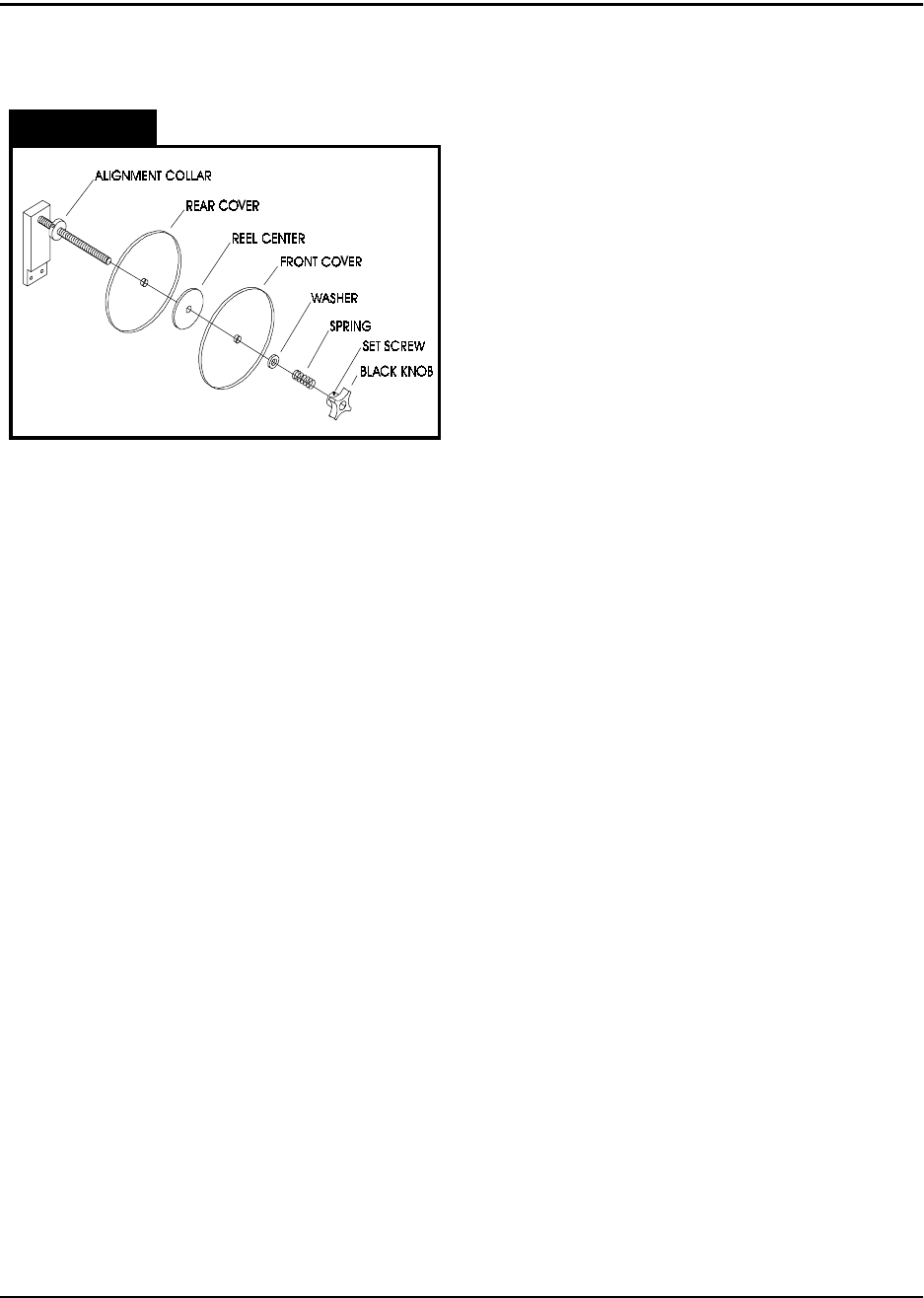
2. Load the Cover Tape
Remove the large black knob from the cover
tape spindle (loosen the brass set screw if
necessary). Remove the spring, washer, and
front plastic cover from the spindle. Place a
reel of cover tape (correct width to match the
carrier tape) on the reel center, so the tape
unwinds to the right from the bottom of the
reel. Replace the plastic cover, washer,
spring, and black knob. Tighten the knob until
there is some tension on the cover tape as it
unwinds, but make sure the tension is not
excessive. Tighten the brass set screw on the
black knob to secure it in place.
3. Load the Carrier Tape
Remove the carrier tape clamp (Fig. 2.2, Ref.
L) from the carrier tape spindle (Fig. 2.2, Ref.
K) and mount the bulk carrier tape reel on the
spindle (the sprocket holes on the carrier tape
must be on the inside). Replace the clamp
and position it so the reel is supported and
spins freely on the spindle. Trim the end of the
carrier tape so it is clean and straight.
The loading track (Fig. 2.2, Ref. P) is adjust-
able for tape width. Set the track width to
match the sealer mounted on the TM-300 by
pulling out, or pushing in, evenly on both ends
of the track. There are detents which will
cause the track to lock in at each tape width.
Open the parts cover (Fig. 2.2, Ref. Q) by lift-
ing on the black knob and remove carrier tape
guide #2 (Fig.2. 2Ref. R) by unscrewing its
black knob. Guide the carrier tape under car-
rier tape guide #1 (Fig. 2.2, Ref. N) and into
the loading track. The carrier tape should feed
through the loading track easily. Lower the
feed reel support arm if necessary to allow the
tape to feed more easily into the loading track.
Bring the end of the tape just up to cover tape
guide #3 (Fig. 2.2, Ref. S).
Setup (cont.)
Figure 2.11
TM-300 Operation Instructions 61170613.fm Page 21 of 27
Setup (cont.)
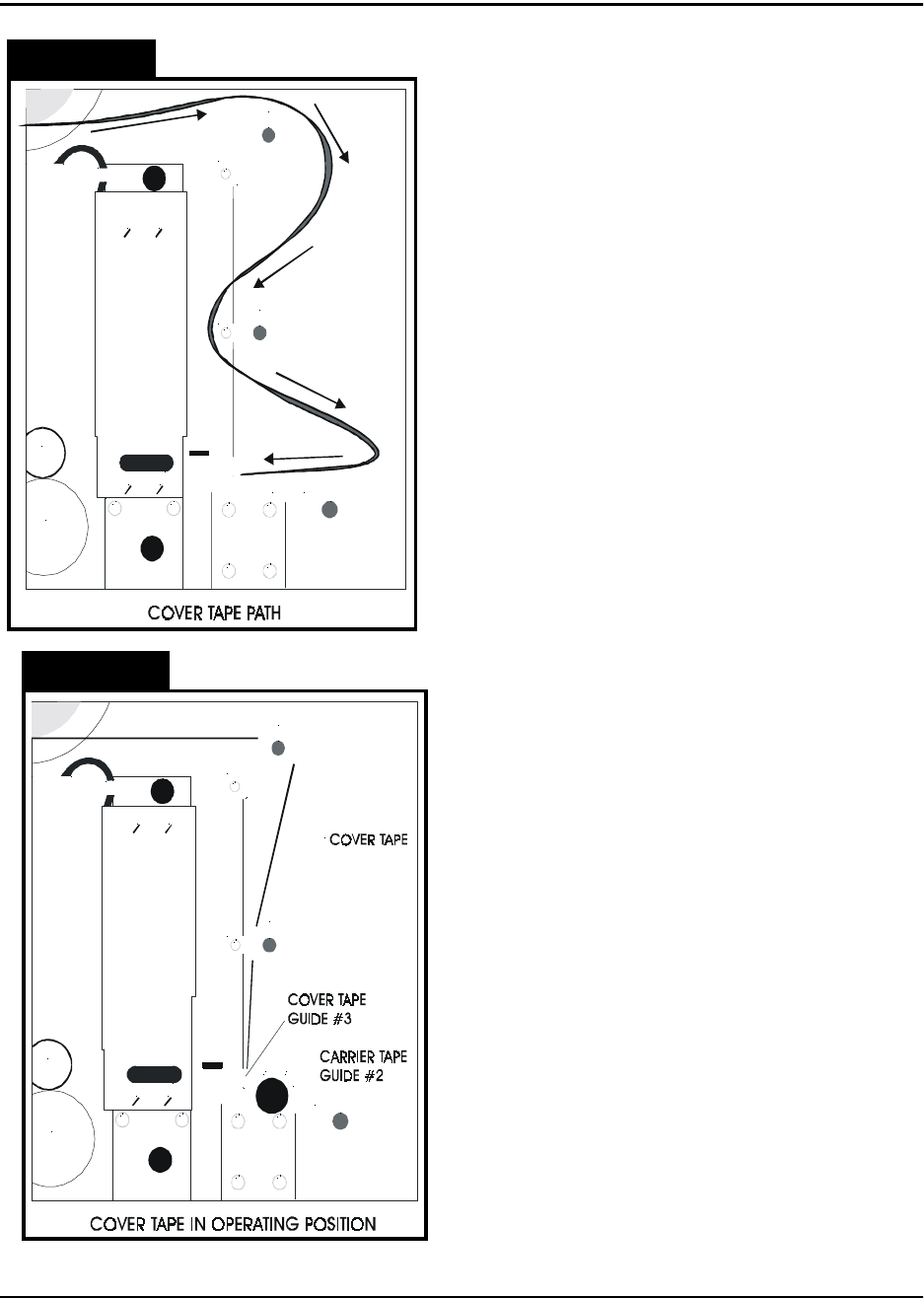
4. Load Tapes into Sealer
Pull the cover tape down through the cover
tape guides as shown. Pull about 12” of cover
tape out and lay it over the carrier tape, with
the free end pointing toward the sealer. The
shiny side of the tape should be up. Allow
about 2” of the free end of the cover tape to
hang over the end of the carrier tape. Push
the tapes under the cover tape guide and
through the sealer by pushing on the carrier
tape. Keep enough slack in the cover tape so
it follows the carrier tape through the sealer.
Lift the idler wheel (Fig. 2.2, Ref. E) by push-
ing down on the left side of the arm. Align the
sprocket holes in the carrier tape over the pins
on the drive sprocket (Fig. 2.2, Ref. F).
Straighten the cover tape so it is aligned with
the carrier tape and rewind any remaining
slack back onto the cover tape reel. Position
the cover tape so it is running in the groove in
cover tape guide #3. Replace carrier tape
guide #2 and screw it down. Close the parts
cover.
5. Mount Take-up Reel
Mount an empty take-up reel on the take-up
reel spindle (Fig. 2.2, Ref. H). The width of the
reel must match the width of the carrier tape
and the reel must be big enough around to
accommodate the number of components in
the taping job.
Figure 2.12
Figure 2.13
TM-300 Operation Instructions 61170613.fm Page 22 of 27
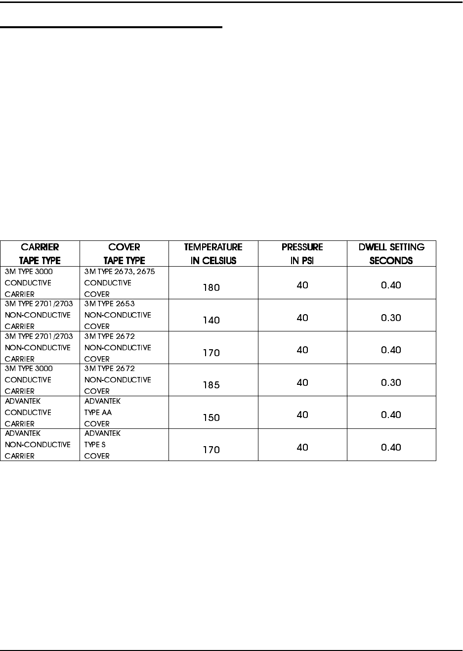
All four factors may be varied on the TM-300
but only the dwell time, seal pressure, and
temperature setting changes are usually
required. The seal width is selected at the fac-
tory and should only require changing under
unusual circumstances. The settings in the
chart are good general starting points to be
used when first learning to use the TM-300.
Experience will suggest variations from these
settings that will provide the desired seal char-
acteristics as determined by a peel force test.
Setup (cont.)
General Seal Setting Information
The cover tape peel force is determined by
four things at the time the cover tape is sealed
to the carrier tape.
These four factors are:
1. The width of the sealing track on the
heat seal shoe.
2. The pressure applied to the seal area.
3. The dwell time, or heating time that the
heat shoe is pressing on the cover tape.
4. The temperature of the seal assembly.
Approximate Starting Points for Seal Controls
°
°
°
°
°
°
***Use this chart as a guide for setting the controls for the first time. These values may need to
be altered due to variations in lot materials and customer requirements.***