TM-300_0wners_Manual.pdf - 第28页
TM-300 Ope ration Ins truct ion s 61170613. fm Page 22 of 27 All fo ur f act ors m a y b e var ied on the TM -300 but on ly th e d well ti me, sea l pre ss ure, and tem pe ratur e setting ch ange s are u suall y req uir …
TM-300 Operation Instructions 61170613.fm Page 21 of 27
Setup (cont.)
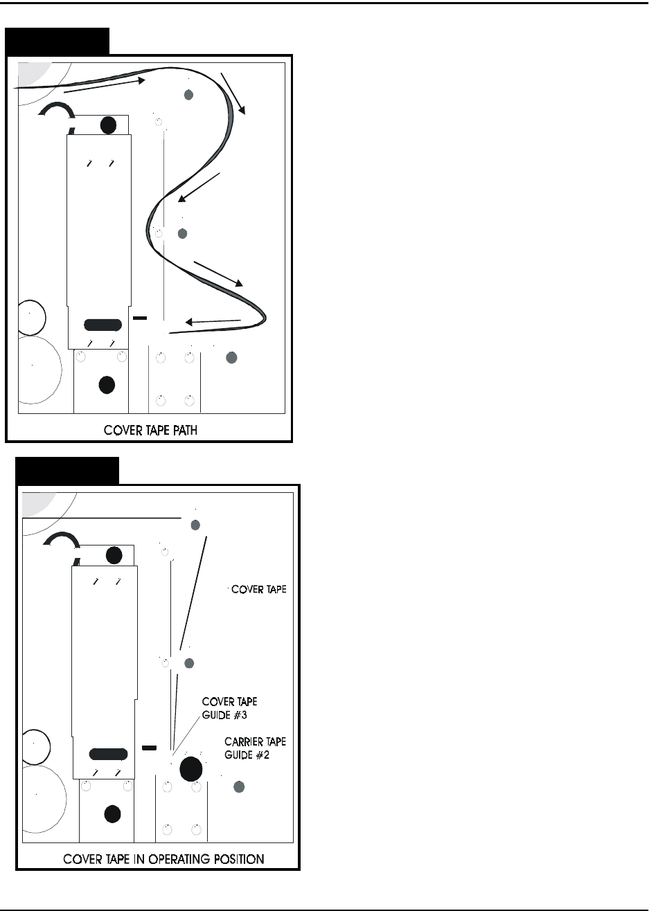
4. Load Tapes into Sealer
Pull the cover tape down through the cover
tape guides as shown. Pull about 12” of cover
tape out and lay it over the carrier tape, with
the free end pointing toward the sealer. The
shiny side of the tape should be up. Allow
about 2” of the free end of the cover tape to
hang over the end of the carrier tape. Push
the tapes under the cover tape guide and
through the sealer by pushing on the carrier
tape. Keep enough slack in the cover tape so
it follows the carrier tape through the sealer.
Lift the idler wheel (Fig. 2.2, Ref. E) by push-
ing down on the left side of the arm. Align the
sprocket holes in the carrier tape over the pins
on the drive sprocket (Fig. 2.2, Ref. F).
Straighten the cover tape so it is aligned with
the carrier tape and rewind any remaining
slack back onto the cover tape reel. Position
the cover tape so it is running in the groove in
cover tape guide #3. Replace carrier tape
guide #2 and screw it down. Close the parts
cover.
5. Mount Take-up Reel
Mount an empty take-up reel on the take-up
reel spindle (Fig. 2.2, Ref. H). The width of the
reel must match the width of the carrier tape
and the reel must be big enough around to
accommodate the number of components in
the taping job.
Figure 2.12
Figure 2.13
TM-300 Operation Instructions 61170613.fm Page 22 of 27
All four factors may be varied on the TM-300
but only the dwell time, seal pressure, and
temperature setting changes are usually
required. The seal width is selected at the fac-
tory and should only require changing under
unusual circumstances. The settings in the
chart are good general starting points to be
used when first learning to use the TM-300.
Experience will suggest variations from these
settings that will provide the desired seal char-
acteristics as determined by a peel force test.
Setup (cont.)
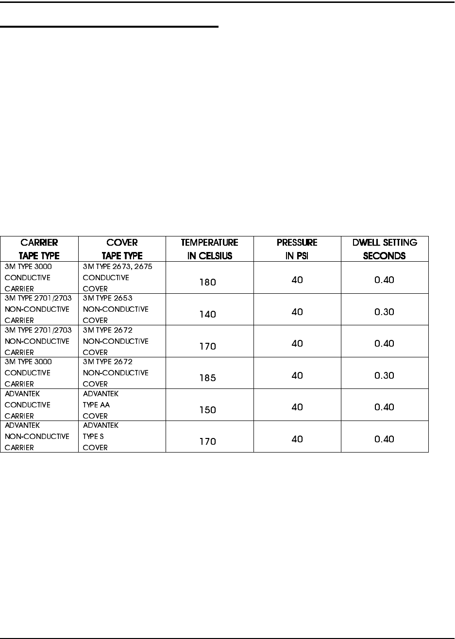
General Seal Setting Information
The cover tape peel force is determined by
four things at the time the cover tape is sealed
to the carrier tape.
These four factors are:
1. The width of the sealing track on the
heat seal shoe.
2. The pressure applied to the seal area.
3. The dwell time, or heating time that the
heat shoe is pressing on the cover tape.
4. The temperature of the seal assembly.
Approximate Starting Points for Seal Controls
°
°
°
°
°
°
***Use this chart as a guide for setting the controls for the first time. These values may need to
be altered due to variations in lot materials and customer requirements.***
TM-300 Operation Instructions 61170613.fm Page 23 of 27
Setup (cont.)
Temperature Controls (cont.)
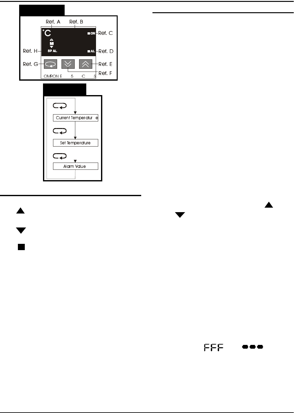
Increment Key (Ref. E)
When pressed, increases the set temperature
value. Successively increases the value when
held down.
Decrement Jey (Ref. F)
When pressed, decreases the set temperature
value. Successively decreases the value
when held down.
Return Key (Ref. G)
Each time pressed, changes the readout on
the main display as shown in Figure 2.15.
Present Data Indicator (Ref. H)
“SP” lights while the set temperature is dis-
played.
Setting the Temperature Controller
1. Press the Return key until the “SP” inicator
lights.
2. Adjust the value by pressing the ( )
or ( ) keys until the desired set temper-
ature is displayed.
3. Press the Return key again to display the
current temperature.
There is one temperature controller for the
inside heat shoe and one for the outside heat
shoe. Normally the two controllers should be
set with the same values, but they can be set
differently if the seal characteristics dictate
that the one controller needs to be set higher
than the other.
Error Messages
If there is a fault (short or open) in the temper-
ature sensor (thermocouple) of the sealer, the
display will flash “ “ or “ “. This
error message will also be displayed if there is
no sealer connected to the TM-300.
Figure 2.14
Figure 2.15
Temperature Controls (Figure 2.14)
Led Deviation Indicator (Ref. A)
The ( ) indicator lights when the current tem-
perature is higher than the set temperature.
The ( ) indicator lights when the current tem-
perature is lower than the set temperature.
The ( ) indicator lights up green when the
current temperature is within the steady state
range of the PID cycle.
Main Display (Ref. B)
Sequentially displays the present temperature,
set temperature, and an alarm value each
time the RETURN key (Ref. G) is pressed.
Control Output Indicator (Ref. C)
Lights while the control output is being pro-
duced.
Alarm Indicator (Ref. D)
If the present temperature exceeds or falls
below the set temperature, by the alarm value,
this indicator will light. This feature is not
implemented on the TM-300 Controller.