TM-300_0wners_Manual.pdf - 第30页
TM-300 Ope ration Ins truct ion s 61170613. fm Page 24 of 27 Setup (con t.) Figur e 2. 16 Figur e 2. 17 Fi gu r e 2. 18 Seal Pr essure Contr ols (Figur e 2.16) Th e sea ler mec hanis m c ont ains t wo s epar ate hea t sh…
TM-300 Operation Instructions 61170613.fm Page 23 of 27
Setup (cont.)
Temperature Controls (cont.)
Increment Key (Ref. E)
When pressed, increases the set temperature
value. Successively increases the value when
held down.
Decrement Jey (Ref. F)
When pressed, decreases the set temperature
value. Successively decreases the value
when held down.
Return Key (Ref. G)
Each time pressed, changes the readout on
the main display as shown in Figure 2.15.
Present Data Indicator (Ref. H)
“SP” lights while the set temperature is dis-
played.
Setting the Temperature Controller
1. Press the Return key until the “SP” inicator
lights.
2. Adjust the value by pressing the ( )
or ( ) keys until the desired set temper-
ature is displayed.
3. Press the Return key again to display the
current temperature.
There is one temperature controller for the
inside heat shoe and one for the outside heat
shoe. Normally the two controllers should be
set with the same values, but they can be set
differently if the seal characteristics dictate
that the one controller needs to be set higher
than the other.
Error Messages
If there is a fault (short or open) in the temper-
ature sensor (thermocouple) of the sealer, the
display will flash “ “ or “ “. This
error message will also be displayed if there is
no sealer connected to the TM-300.
Figure 2.14
Figure 2.15
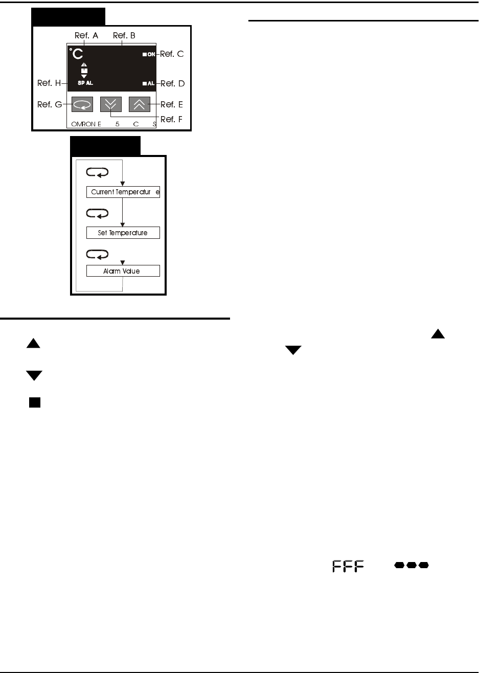
Temperature Controls (Figure 2.14)
Led Deviation Indicator (Ref. A)
The ( ) indicator lights when the current tem-
perature is higher than the set temperature.
The ( ) indicator lights when the current tem-
perature is lower than the set temperature.
The ( ) indicator lights up green when the
current temperature is within the steady state
range of the PID cycle.
Main Display (Ref. B)
Sequentially displays the present temperature,
set temperature, and an alarm value each
time the RETURN key (Ref. G) is pressed.
Control Output Indicator (Ref. C)
Lights while the control output is being pro-
duced.
Alarm Indicator (Ref. D)
If the present temperature exceeds or falls
below the set temperature, by the alarm value,
this indicator will light. This feature is not
implemented on the TM-300 Controller.
TM-300 Operation Instructions 61170613.fm Page 24 of 27
Setup (cont.)
Figure 2.16
Figure 2.17
Figure 2.18
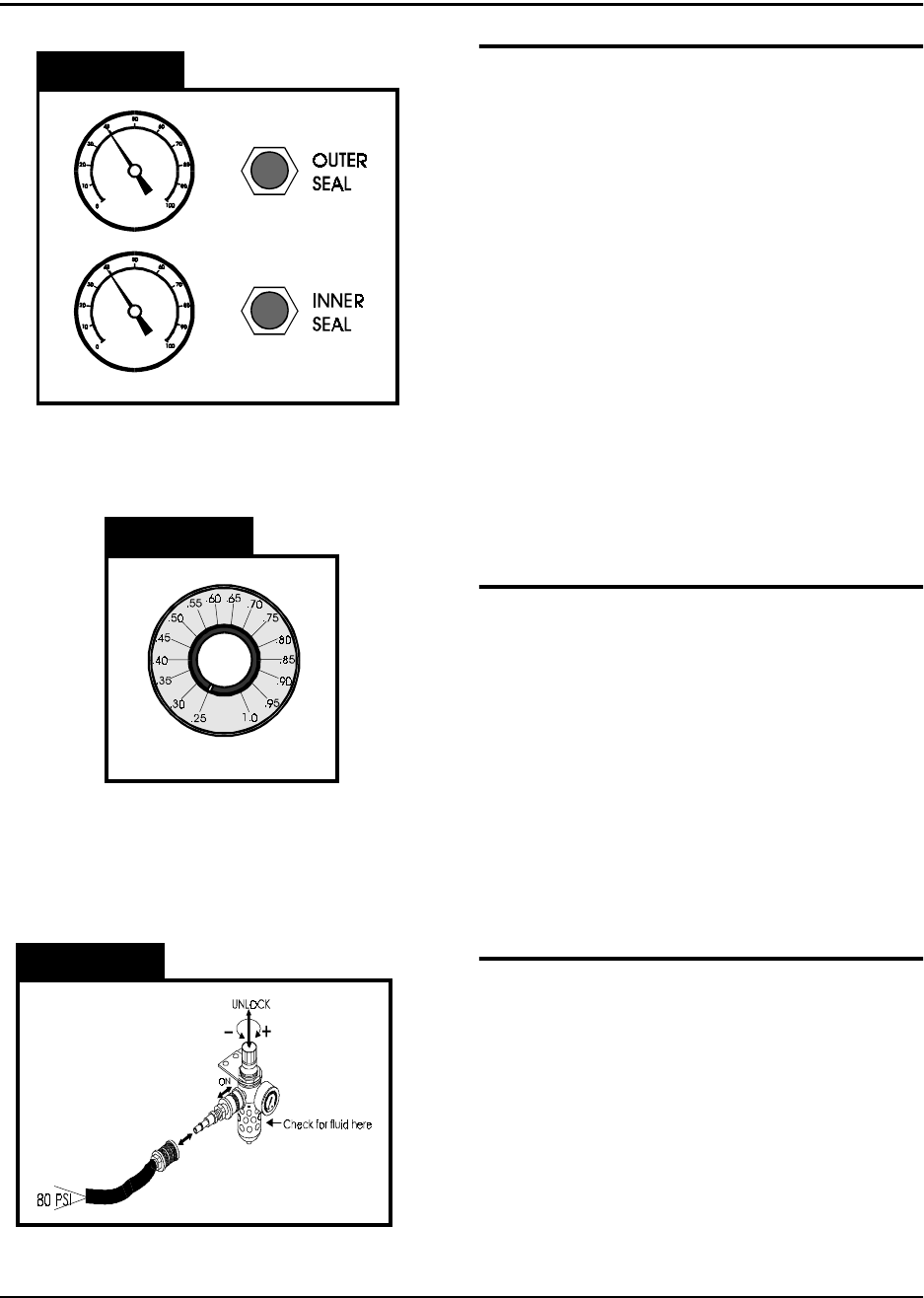
Seal Pressure Controls (Figure 2.16)
The sealer mechanism contains two separate
heat shoes which have independent controls
for heat and pressure. The pressure gauges
on the front of the TM-300 indicate the amount
of air pressure in the sealing systems for each
heat shoe. The controls for adjusting this air
pressure are located directly beside the pres-
sure gauges. Turning a control clockwise will
increase the amount of pressure applied to the
associated heat shoe. Normally the two sys-
tems should be set at the same pressure, but
they can be set differently if the seal charac-
teristics dictate that one be set higher than the
other. When taping some very small SMD
components, it may be necessary to decrease
the seal pressure to reduce the shock applied
to the carrier tape when sealing.
Seal Dwell Control (Figure 2.17)
The dwell control selects the amount of time
the heat shoes are in contact with the tape
when the sealer is activated. The dwell time is
always the same for both heat shoes. The dial
on the control reads from .25 to 1.0 seconds in
increments of 0.05. These numbers represent
the actual time the seal heads dwell on the
cover tape. Set the control as shown in the
approximate settings chart for initial set-up.
Experience and peel force tests on sealed
tape will dictate changes from these values.
Attach Air Supply (Figure 2.18)
Connect an air-supply hose (at least 80 PSI)
to the input regulator on the left, rear side of
the TM-300. Slide the air cut-off switch for-
ward to apply air pressure to the TM-300. Pull
up on the regulator control knob and turn it
(clockwise increases pressure) until the gauge
registers 80 PSI. Push the regulator control
knob back down to lock it into position. To
remove air pressure to the TM-300 at any
time, slide the air cut-off switch back.
TM-300 Operation Instructions 61170613.fm Page 25 of 27
Operation
Figure 2.19
Figure 2.20
Refer to Figures 2.19 and 2.20 for information
on this page.
Initial Procedures
1. Set the Take-up Reel Adjust control to 0
(fully CCW).
2. Turn the TM-300 main power switch ON.
3. Perform the Taping Assembly Setup pro-
cedures described in this manual.
4. Set the Counter Module Preset and Pres-
cale values.
5. Set the sealer controls at the appropriate
levels. Wait for the temperature controls
to stabilize near their set temperature.
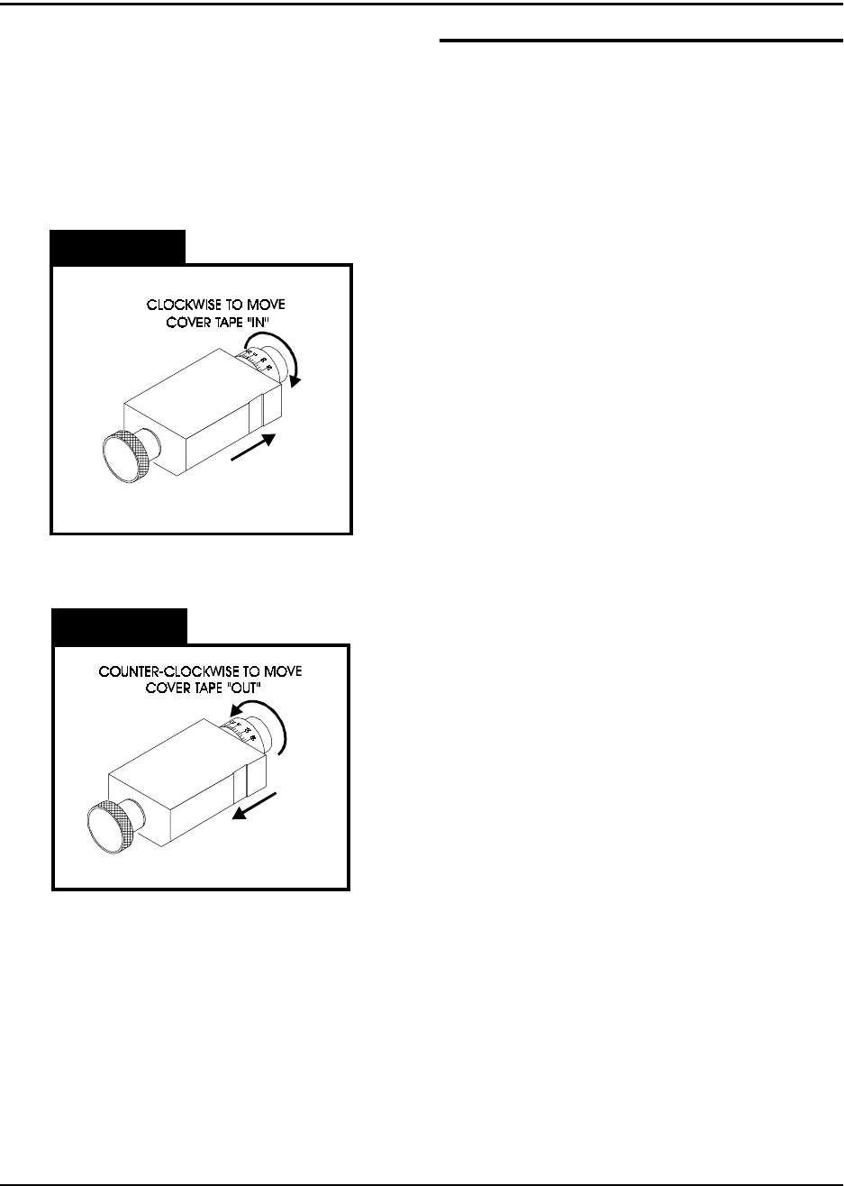
To move the cover tape in relation to the car-
rier, loosen the knob on cover tape guide #3
and pull the guide slightly away from the
adjustment dial so the dial will turn freely.
Turning the dial clockwise will move the cover
tape closer to the sprocket holes on the inside
edge of the carrier (ten divisions on the dial
will move the tape .005 inches).
Turning the dial counter-clockwise will move
the cover tape closer to the outside edge of
the carrier (ten divisions on the dial will move
the tape .005 inches).
Push the tape guide back against the dial after
the adjustment has been made and tighten
the knob. Run the tape out again until the
cover tape stops shifting and check the align-
ment. Repeat this procedure until the proper
alignment has been achieved.
Peel Force
In most taping applications a peel force test is
needed to determine the seal characteristics.
Take as many peel force tests as are needed,
while adjusting the sealer controls, to obtain
the desired seal.