TM-300_0wners_Manual.pdf - 第31页
TM-300 Ope ration Ins truct ion s 61170613. fm Page 25 of 27 Opera tion Fi gu r e 2. 19 Figur e 2. 20 Refer to Fig ures 2.19 and 2. 20 fo r infor mati on on t his pa ge . Initial Pr ocedures 1. Set the T ak e- up Reel A …
TM-300 Operation Instructions 61170613.fm Page 24 of 27
Setup (cont.)
Figure 2.16
Figure 2.17
Figure 2.18
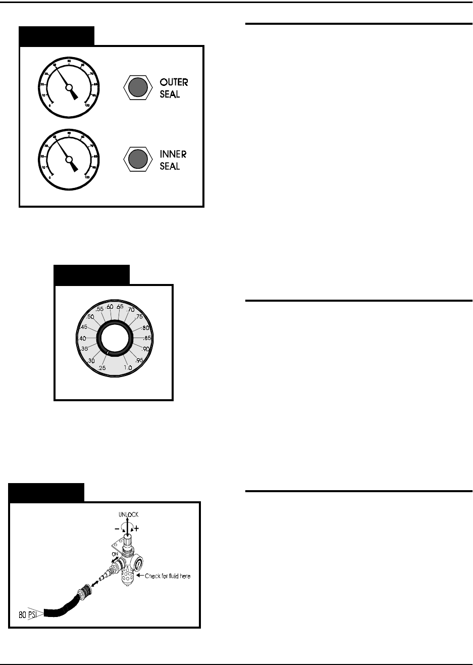
Seal Pressure Controls (Figure 2.16)
The sealer mechanism contains two separate
heat shoes which have independent controls
for heat and pressure. The pressure gauges
on the front of the TM-300 indicate the amount
of air pressure in the sealing systems for each
heat shoe. The controls for adjusting this air
pressure are located directly beside the pres-
sure gauges. Turning a control clockwise will
increase the amount of pressure applied to the
associated heat shoe. Normally the two sys-
tems should be set at the same pressure, but
they can be set differently if the seal charac-
teristics dictate that one be set higher than the
other. When taping some very small SMD
components, it may be necessary to decrease
the seal pressure to reduce the shock applied
to the carrier tape when sealing.
Seal Dwell Control (Figure 2.17)
The dwell control selects the amount of time
the heat shoes are in contact with the tape
when the sealer is activated. The dwell time is
always the same for both heat shoes. The dial
on the control reads from .25 to 1.0 seconds in
increments of 0.05. These numbers represent
the actual time the seal heads dwell on the
cover tape. Set the control as shown in the
approximate settings chart for initial set-up.
Experience and peel force tests on sealed
tape will dictate changes from these values.
Attach Air Supply (Figure 2.18)
Connect an air-supply hose (at least 80 PSI)
to the input regulator on the left, rear side of
the TM-300. Slide the air cut-off switch for-
ward to apply air pressure to the TM-300. Pull
up on the regulator control knob and turn it
(clockwise increases pressure) until the gauge
registers 80 PSI. Push the regulator control
knob back down to lock it into position. To
remove air pressure to the TM-300 at any
time, slide the air cut-off switch back.
TM-300 Operation Instructions 61170613.fm Page 25 of 27
Operation
Figure 2.19
Figure 2.20
Refer to Figures 2.19 and 2.20 for information
on this page.
Initial Procedures
1. Set the Take-up Reel Adjust control to 0
(fully CCW).
2. Turn the TM-300 main power switch ON.
3. Perform the Taping Assembly Setup pro-
cedures described in this manual.
4. Set the Counter Module Preset and Pres-
cale values.
5. Set the sealer controls at the appropriate
levels. Wait for the temperature controls
to stabilize near their set temperature.
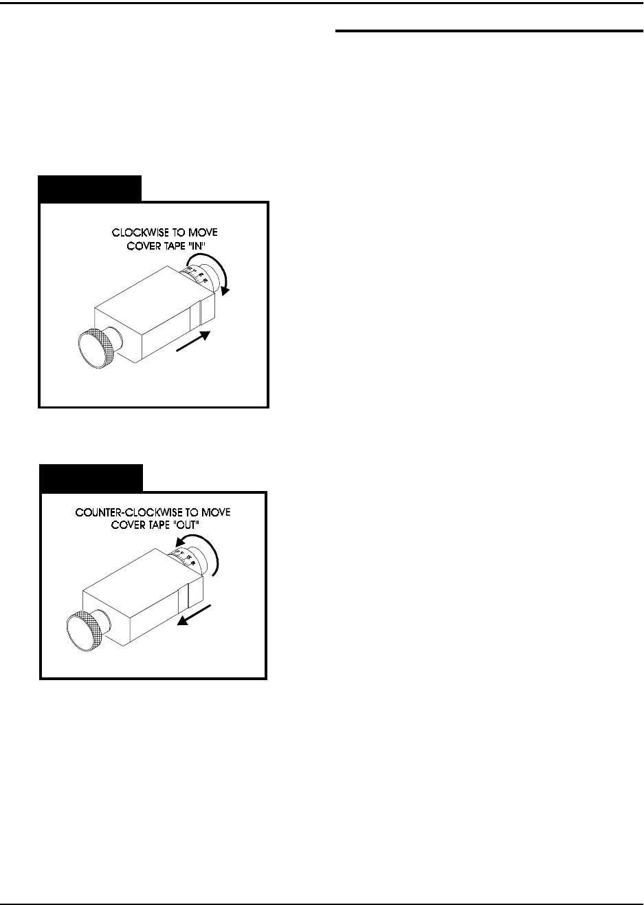
To move the cover tape in relation to the car-
rier, loosen the knob on cover tape guide #3
and pull the guide slightly away from the
adjustment dial so the dial will turn freely.
Turning the dial clockwise will move the cover
tape closer to the sprocket holes on the inside
edge of the carrier (ten divisions on the dial
will move the tape .005 inches).
Turning the dial counter-clockwise will move
the cover tape closer to the outside edge of
the carrier (ten divisions on the dial will move
the tape .005 inches).
Push the tape guide back against the dial after
the adjustment has been made and tighten
the knob. Run the tape out again until the
cover tape stops shifting and check the align-
ment. Repeat this procedure until the proper
alignment has been achieved.
Peel Force
In most taping applications a peel force test is
needed to determine the seal characteristics.
Take as many peel force tests as are needed,
while adjusting the sealer controls, to obtain
the desired seal.

TM-300 Operation Instructions 61170613.fm Page 26 of 27
Placing Parts
Starting with the left-most pocket, place a part
in each empty pocket for the full length of the
loading track. Close the parts cover (Fig.2.2,
Ref. Q) if desired. Press on the foot switch to
advance the carrier tape through the taping
assembly. Stop the tape advance prior to an
empty pocket reaching carrier tape guide #2
and refill the carrier tape in the loading track.
Repeat until the trailer has advanced to a posi-
tion where the end of the sealed tape reaches
the take-up reel and attach it to the inside hub
of the reel. Adjust the take-up reel tension with
just enough tension to wrap the tape on the
take-up reel. DO NOT APPLY EXCESSIVE
TENSION. Use only enough tension to wrap
the tape. Adjust tension as needed as parts
are added. Continue taping parts until the
counter module reaches its Preset value and
stops the tape advance.
To End Taping
Preset
When the End Count value on the counter
module is reached, the TM-300 will stop. The
last part to pass under carrier tape guide #2
will be the last part counted. Any additional
parts in the loading track must be removed.
Reset
Press the RST button on the counter module to
enable taping of the leader.
Leader
Seal the desired number of empty pockets.
When the last sealed empty pocket has
cleared the drive sprocket, cut the tape just to
the left of the sprocket.
Operation (cont.)
To Begin Taping
Leader/Trailer
Before beginning a production reel, you must
decide how long the trailer and the leader
need to be.
Trailer - The strip of empty pockets needed
at the end of the reel.
Leader - The strip of empty pockets needed
at the beginning of the reel to feed into a
pick and place machine.
The trailer of each reel is taped first. After the
cover tape alignment and any peel force tests
are completed, run out enough sealed empty
pockets to make the trailer. After the trailer is
taped, check the counter display to ensure it
reads 0. If not, press the counter module
RESET button.
Tape Alignment
To ensure an accurate count, the first pocket
in the loading track (left-most) must be a full
pocket. That is, the left-most edge of the
pocket must be aligned with the right edge of
carrier tape guide #2 (Fig. 2.2, Ref. R). If a full
pocket is not showing, lift the carrier tape free
of the drive sprocket and move it back until a
full pocket is showing, then engage the carrier
tape on the drive sprocket at that point.
Counter Enable
Verify that the COUNTER ENABLE SWITCH
is UP and that the counter has been reset.