TM-300_0wners_Manual.pdf - 第33页
TM-300 Ope ration Ins truct ion s 61170613. fm Page 27 of 27 Maint enance Figur e 2. 21 Seal Assembly DO NOT T OUCH THE HE A T SHOE ASSEM- BL Y WHEN IT IS HO T! IT WILL STAY HOT ENOUGH TO BURN FINGERS SEVERAL MINUTES AFT…

TM-300 Operation Instructions 61170613.fm Page 26 of 27
Placing Parts
Starting with the left-most pocket, place a part
in each empty pocket for the full length of the
loading track. Close the parts cover (Fig.2.2,
Ref. Q) if desired. Press on the foot switch to
advance the carrier tape through the taping
assembly. Stop the tape advance prior to an
empty pocket reaching carrier tape guide #2
and refill the carrier tape in the loading track.
Repeat until the trailer has advanced to a posi-
tion where the end of the sealed tape reaches
the take-up reel and attach it to the inside hub
of the reel. Adjust the take-up reel tension with
just enough tension to wrap the tape on the
take-up reel. DO NOT APPLY EXCESSIVE
TENSION. Use only enough tension to wrap
the tape. Adjust tension as needed as parts
are added. Continue taping parts until the
counter module reaches its Preset value and
stops the tape advance.
To End Taping
Preset
When the End Count value on the counter
module is reached, the TM-300 will stop. The
last part to pass under carrier tape guide #2
will be the last part counted. Any additional
parts in the loading track must be removed.
Reset
Press the RST button on the counter module to
enable taping of the leader.
Leader
Seal the desired number of empty pockets.
When the last sealed empty pocket has
cleared the drive sprocket, cut the tape just to
the left of the sprocket.
Operation (cont.)
To Begin Taping
Leader/Trailer
Before beginning a production reel, you must
decide how long the trailer and the leader
need to be.
Trailer - The strip of empty pockets needed
at the end of the reel.
Leader - The strip of empty pockets needed
at the beginning of the reel to feed into a
pick and place machine.
The trailer of each reel is taped first. After the
cover tape alignment and any peel force tests
are completed, run out enough sealed empty
pockets to make the trailer. After the trailer is
taped, check the counter display to ensure it
reads 0. If not, press the counter module
RESET button.
Tape Alignment
To ensure an accurate count, the first pocket
in the loading track (left-most) must be a full
pocket. That is, the left-most edge of the
pocket must be aligned with the right edge of
carrier tape guide #2 (Fig. 2.2, Ref. R). If a full
pocket is not showing, lift the carrier tape free
of the drive sprocket and move it back until a
full pocket is showing, then engage the carrier
tape on the drive sprocket at that point.
Counter Enable
Verify that the COUNTER ENABLE SWITCH
is UP and that the counter has been reset.
TM-300 Operation Instructions 61170613.fm Page 27 of 27
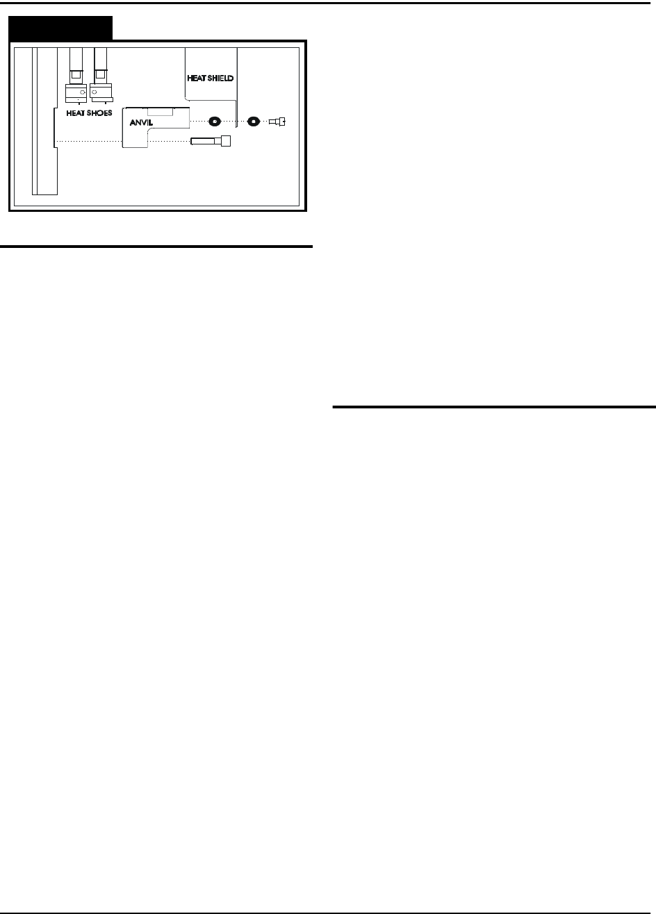
Maintenance
Figure 2.21
Seal Assembly
DO NOT TOUCH THE HEAT SHOE ASSEM-
BLY WHEN IT IS HOT! IT WILL STAY HOT
ENOUGH TO BURN FINGERS SEVERAL
MINUTES AFTER THE SEALER HAS BEEN
TURNED OFF!
Heat Sealer
Heat sealer maintenance consists mainly of
cleaning built-up residues from the heat
shoes. These residues occur due to a mixture
of dust, tape debris, and cover tape adhesive
which accumulate during taping. Remove the
two bottom screws holding the heat shield to
the sealer. Be careful not to lose the O-rings
which are under the head of these screws and
between the heat shield and the anvil.
Remove the two bolts which hold the anvil to
the sealer assembly. Remove the anvil by
sliding it to one side.
*CAUTION* - DO NOT USE ALCOHOL ON A
HOT SEALER.
Clean the residues from the heat shoes by
using a plastic or brass brush soaked in alco-
hol. DO NOT USE A STEEL BRISTLED
BRUSH. If there are some tough spots, such
as melted plastic, which do not want to come
clean, the sealer can be heated by plugging it
into the taping machine, and then scraped
with the handle of a wood brush or some other
wooden implement.
Alignment
If the seal becomes uneven, where one end of
the heat shoe seems to be striking harder than
the other, DO NOT DISASSEMBLE THE HEAT
SHOE ASSEMBLY. To realign the heat shoes
the sealer must be sent back to the factory.
O-Rings
There are five O-rings between the sealer
assembly and the seal assembly up-right which
provide a seal between the two for the air pres-
sure that drives the sealer. When changing
sealer assemblies, check that these O-rings are
in place and not damaged. When replacing,
place a small amount of adhesive, such as
super glue, on the O-ring before inserting into
the recess. Make sure that the airway is not
blocked.
Tape Path
Loading Track
Occasionally, when the machine is stripped and
cover tape guide #3 is removed, brush the dust
and debris from the track with a small, stiff bris-
tled paint brush.
Cover Tape Guide #3
This may become coated with adhesive and dirt
during taping. It is important to keep the tape
groove clean for proper alignment of the cover
tape. Clean the tape groove with alcohol and a
cotton swab whenever it appears dirty.
Encoder Wheel
The slotted wheel and adjacent sensors may
become covered in dust and debris which may
cause erroneous counting. Brush these off with
a stiff bristled brush whenever they appear dirty.
Air Pressure Regulator
Inspect the air regulator for moisture accumula-
tion (see page 22). Check periodically depend-
ing on air quality and press the petcock on the
bottom of regulator to release the fluid if mois-
ture is present.

TM-300 Index 61201910.FM Page 1 of 2
TM-300
Index
Numbers
115vac (ac power input) 13
A
adjustable loading track 9
air pressure on/off switch 9
air pressure regulator 27
air regulator 13
alarm indicator 23
alignment 27
approximate starting points
for seal controls 22
assembling procedure 6, 7
attach air supply 24
attention 3
C
carrier tape quide #1 9
carrier tape guide #2 9
carrier tape type 22
carrier tape quick lock 9
caution 4
changing the end count value
15
control module 6
control module base plate 6
control output indicator 23
controller operation 16
controller setup 17
count 12
count enable switch 14
count sensor 10
counter 12
counter controls 14
counter enable 26
counter module 14
cover tape alignment 26
cover tape guide #1 6, 9
cover tape guide #2 9
cover tape guide #3 10, 27
cover tape reel spindle 9
cover tape reel support 6
cover tape type 22
crushed hand
D
dangerous voltage 3, 4
download operation 18
drive motor 10
drive sprocket 9
dwell 12, 16
dwell setting seconds 22
E
encoder wheel 27
ent (enter) 14
error messages 23
F
feed reel support arm 6
follower track support arm 6,
10
fsw (footswitch) 13, 16
fuse 13
fwd button 11, 16
G
general seal setting informa-
tion 22
H
heat sealer 27
heat sealer assembly 10
high temperature 3
I
i/o (input/output) 13
idler arm 10
idler wheel 9
increment/decrement key
(+/-) 14, 23
initial procedures 25
inner seal 12
J
jog mode (tape adjust) 16
jog/run switch 11
L
leader 26
led deviation indicator 23
load tapes into the sealer 21
load the carrier tape 20
load the cover tape 20
loading track 27
M
main display 23
maintenance 27
marking definitions 3
mechanical assembly 9, 10
mount heat sealer assembly
19
mount take-up reel 21
N
next digit 14
O
open book 3
operation 25, 26
operation instructions 5
operating controls 11-13
outer seal 12
o-rings 19, 27
P
pc setup 18
parts cover 9
peel force 26
peripheral 13
pitch 12, 16
pitch setting guide 9
placing parts 26
power switch 11
present data indicator 23
preset 26
pressure in psi 22
pst (preset select) 14
R
rst (reset) 13, 14, 26
rev button 11, 16
rs-232 connector 13
run mode 16