TM-300_0wners_Manual.pdf - 第6页
TM-300 I/ O Con nector 61170410. fm Page 1 of 1 Pu rpose: Th e pu rpose of this doc ument is to help guide you th roug h the p rocess of addi ng a m od ule to the TM-30 0 us ing the I/O conne c- tor on the bac k of the m…
TM-300 Options 61170310.fm Page 1 of 1
TM-300 Options
Introduction
On this page is a list of the options that can be
custom installed on the TM-300 Taping
Machine. The disk included with the machine
contains a program and readme file for the
purpose of integrating your TM-300 with other
robotic equipment.
Empty Pocket Detector
The empty pocket detector is a sensor that is
used to detect an empty carrier tape pocket.
There are a variety of sensors that can be fit-
ted to meet various needs.
Automated Integration
The TM-300 can be integrated with existing
robotic equipment to perform a variety of dif-
ferent tasks.
Low Cover Tape
Upon integration, a sensor can be installed
that notifies the operator that the machine is
low on cover tape.
Low Carrier Tape
Upon integration, a sensor can be installed
that notifies the operator that the machine is
low on carrier tape.
Please contact your V-TEK representative
for more information on any of the options
mentioned on this page.
TM-300 I/O Connector 61170410.fm Page 1 of 1
Purpose:
The purpose of this document is to
help guide you through the process of adding
a module to the TM-300 using the I/O connec-
tor on the back of the machine as shown in
Figure 1. WARNING: ONLY QUALIFIED
PERSONS ARE TO PERFORM THIS PRO-
CEDURE!
TM-300 I/O Specifications
I/O Connector Description Internal Connection
Pin #1 Input (1) Supply C.B. #7 (IN1)
Pin #2 Input (2) Supply C.B. #8
(IN2)
Pin #3 Output (1) Supply C.B. #12
(OUT1)
Pin #4 Logic Com.Supply C.B. #14
(COMM)
Step 1. Make a 9 pin female AMP connector
according to the steps below. If you
need to order a connector and pins,
please contact your V-TEK represen-
tative.
Step 2. Prepare pin 4. All external I/O cir-
cuitry must be connected to this COM-
MON in order for the controller to
respond properly to the module.
Step 3. Prepare pin 1 (pin 2 is used for addi-
tional software). The software can be
structured around this input to allow
control of various machine functions.
The input is connected to a small sig-
nal relay. The input is active when the
external line is pulled to COMMON.
There is an internal pull-up resistor
(10K, 1/4W) which normally holds the
external input line at +15VDC.
Step 4. Prepare pin 3. The output signal is an
indication of MOTION BUSY. It is a
transistor, open collector output (SINK-
ING) and does NOT have short circuit
protection. When the TM-300 motor is
in motion the external output line will
be floating.
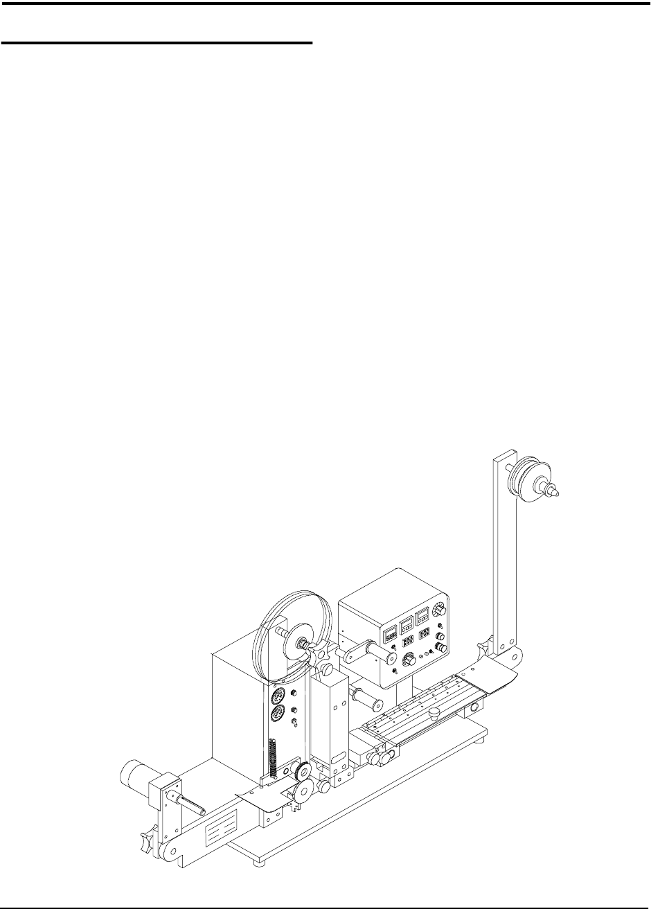
The TM-300 I/O Connector
Unused
Unused
Unused
Unused
I/O Pin 4
(Logic COM)
I/O Pin 3
(“Motion Busy”
Output Signal)
I/O Pin 2
(Software
Input-5)
I/O Pin 1
(Software
Input-6)
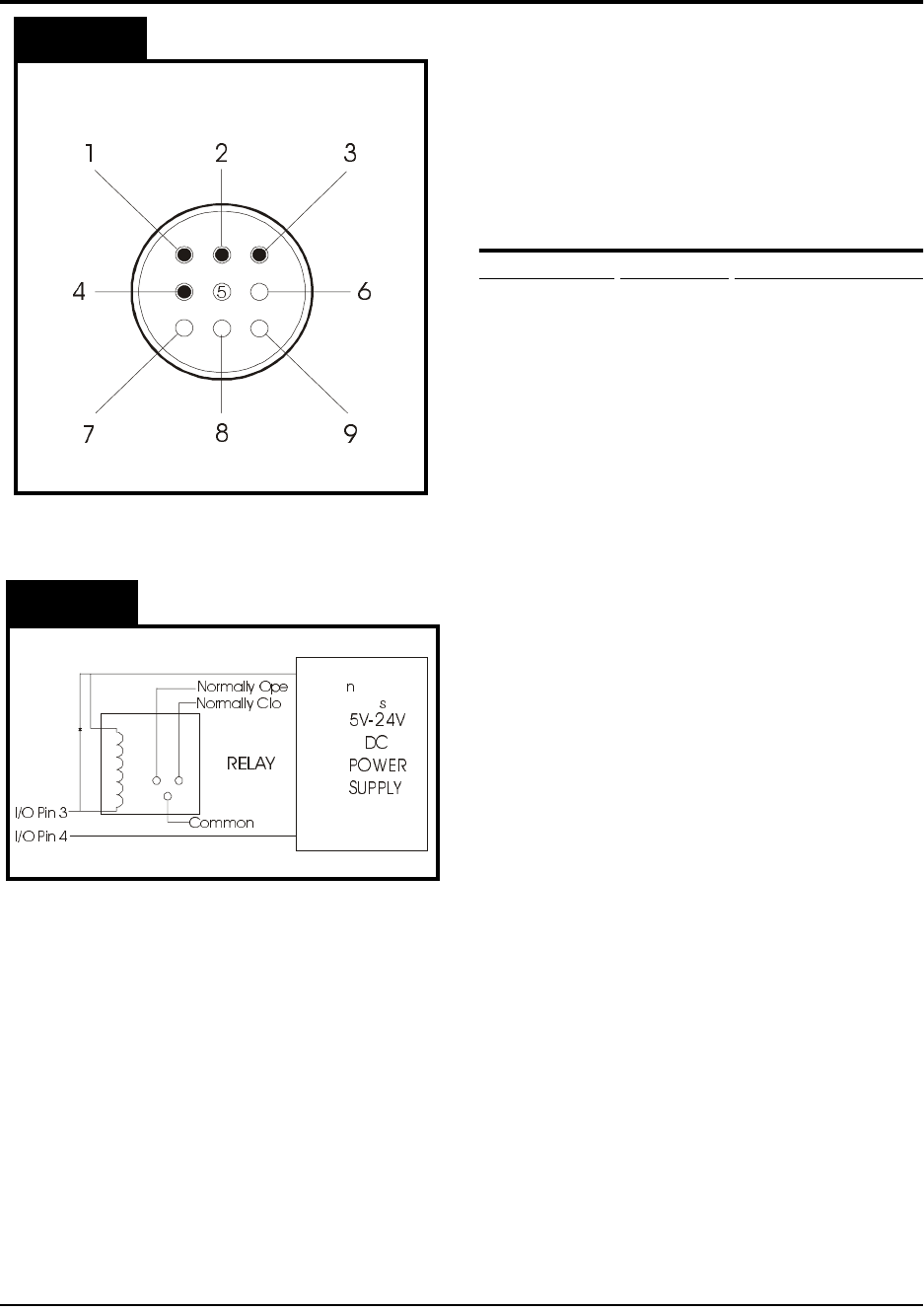
NOTE:
Figure 2 is a schematic for an
Figure 2
Figure 1
EXAMPLE CIRCUIT with a relay
connected to an outside power source
.
Due to the customization of the I/O
connector, please contact your V-TEK
representative for additional information.

TM-300 Safety Instructions 61170511.fm Page 1 of 27
Chapter 1
Safety Instructions
This chapter describes the procedures you must follow to safely operate the TM-300. Read all
instructions before operating the TM-300 and keep them for future reference.
Chapter 1
Safety Instructions
Safety Introduction..............................................2
Marking Definitions .............................................3
Safety Instructions ..............................................4