TM-300_0wners_Manual.pdf - 第7页
TM-300 Saf e ty In struc tio ns 61170511. fm Page 1 of 27 Chapter 1 Safety Inst r u ctions This chapte r de scribe s the pro cedu res y ou mu st fol low to s afe ly ope r ate the T M-300. Rea d all instru ctio ns be fore…
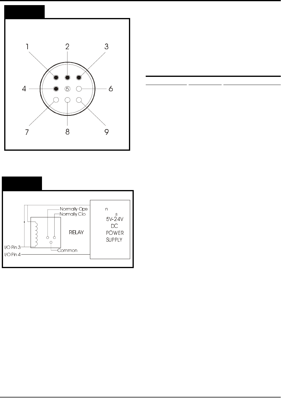
TM-300 I/O Connector 61170410.fm Page 1 of 1
Purpose:
The purpose of this document is to
help guide you through the process of adding
a module to the TM-300 using the I/O connec-
tor on the back of the machine as shown in
Figure 1. WARNING: ONLY QUALIFIED
PERSONS ARE TO PERFORM THIS PRO-
CEDURE!
TM-300 I/O Specifications
I/O Connector Description Internal Connection
Pin #1 Input (1) Supply C.B. #7 (IN1)
Pin #2 Input (2) Supply C.B. #8
(IN2)
Pin #3 Output (1) Supply C.B. #12
(OUT1)
Pin #4 Logic Com.Supply C.B. #14
(COMM)
Step 1. Make a 9 pin female AMP connector
according to the steps below. If you
need to order a connector and pins,
please contact your V-TEK represen-
tative.
Step 2. Prepare pin 4. All external I/O cir-
cuitry must be connected to this COM-
MON in order for the controller to
respond properly to the module.
Step 3. Prepare pin 1 (pin 2 is used for addi-
tional software). The software can be
structured around this input to allow
control of various machine functions.
The input is connected to a small sig-
nal relay. The input is active when the
external line is pulled to COMMON.
There is an internal pull-up resistor
(10K, 1/4W) which normally holds the
external input line at +15VDC.
Step 4. Prepare pin 3. The output signal is an
indication of MOTION BUSY. It is a
transistor, open collector output (SINK-
ING) and does NOT have short circuit
protection. When the TM-300 motor is
in motion the external output line will
be floating.
The TM-300 I/O Connector
Unused
Unused
Unused
Unused
I/O Pin 4
(Logic COM)
I/O Pin 3
(“Motion Busy”
Output Signal)
I/O Pin 2
(Software
Input-5)
I/O Pin 1
(Software
Input-6)
NOTE:
Figure 2 is a schematic for an
Figure 2
Figure 1
EXAMPLE CIRCUIT with a relay
connected to an outside power source
.
Due to the customization of the I/O
connector, please contact your V-TEK
representative for additional information.

TM-300 Safety Instructions 61170511.fm Page 1 of 27
Chapter 1
Safety Instructions
This chapter describes the procedures you must follow to safely operate the TM-300. Read all
instructions before operating the TM-300 and keep them for future reference.
Chapter 1
Safety Instructions
Safety Introduction..............................................2
Marking Definitions .............................................3
Safety Instructions ..............................................4

TM-300 Safety Instructions 61170511.fm Page 2 of 27
In this document you will find:
* important safety guidelines to follow when
operating the equipment.
* important definitions of safety markings.
WARNING: Read the provided manuals
thoroughly before attempting to operate
this machine.
Customers who intend to service and maintain
the TM-300 themselves must only have quali-
fied personnel perform those procedures.
Qualified personnel are considered to be
those persons who have the proper technical
training, have experience to work on this
equipment, and are aware of the hazards to
which they will be exposed. The Service Man-
ual is intended to be a supplement to training
(NOT A REPLACEMENT).
ATTENTION: Place the TM-300 on a stable,
flat surface before operating.
The intended use of the TM-300 Taping
Machine is to place Surface Mount compo-
nents into carrier tape. Use of this equipment
in any other fashion may lead to personal
injury.
The safety guidelines provided on the follow-
ing pages are intended to educate the user on
all safety issues in order to operate the TM-
300 in a safe manner.
Pay close attention to these statements as
they contain important information on avoiding
potential hazards to yourself or to the equip-
ment.
Safety Introduction