TRS Advanced WB Intel Issue 02.pdf - 第104页
TRS Advanced Maintenance 104 Issue 2, Nov 14 Objective 34: Calibrate Rail Width using Technical Reference Manual .
Issue 2, Nov 14
TRS Advanced Maintenance
103
Objective 33: Calibrate Print Height:
NOTE
Do not fit the 212272 Shim for this procedure. It is easier to see screen deformation.
1. Load the screen to the printer.
2. In Diagnostics, select Set Reference Print Height from the Rising Table module.
3. Adjust the print height using INCR/DECR & MOVE until the Rail Cap foils are seen to
slightly deform the screen.
4. Adjust the Rising Table back down until the Rail Cap Foils are clear of the screen.
NOTE
The gap between screen & foils should be AS SMALL AS POSSIBLE.
Fine tune the height by jogging the Table UP & DOWN until a single jog is
enough to visibly DEFORM or UNDEFORM the screen.
5. Select SET Height and save the setting to the configuration file.
6. HOME the Rising Table.
7. Drive the Rising Table to PRINT Height (to confirm the height setting).
8. HOME the Rising Table again.
9. UNLOAD the Calibration Screen.

TRS Advanced Maintenance
104
Issue 2, Nov 14
Objective 34: Calibrate Rail Width using Technical Reference Manual.
Issue 2, Nov 14
TRS Advanced Maintenance
105
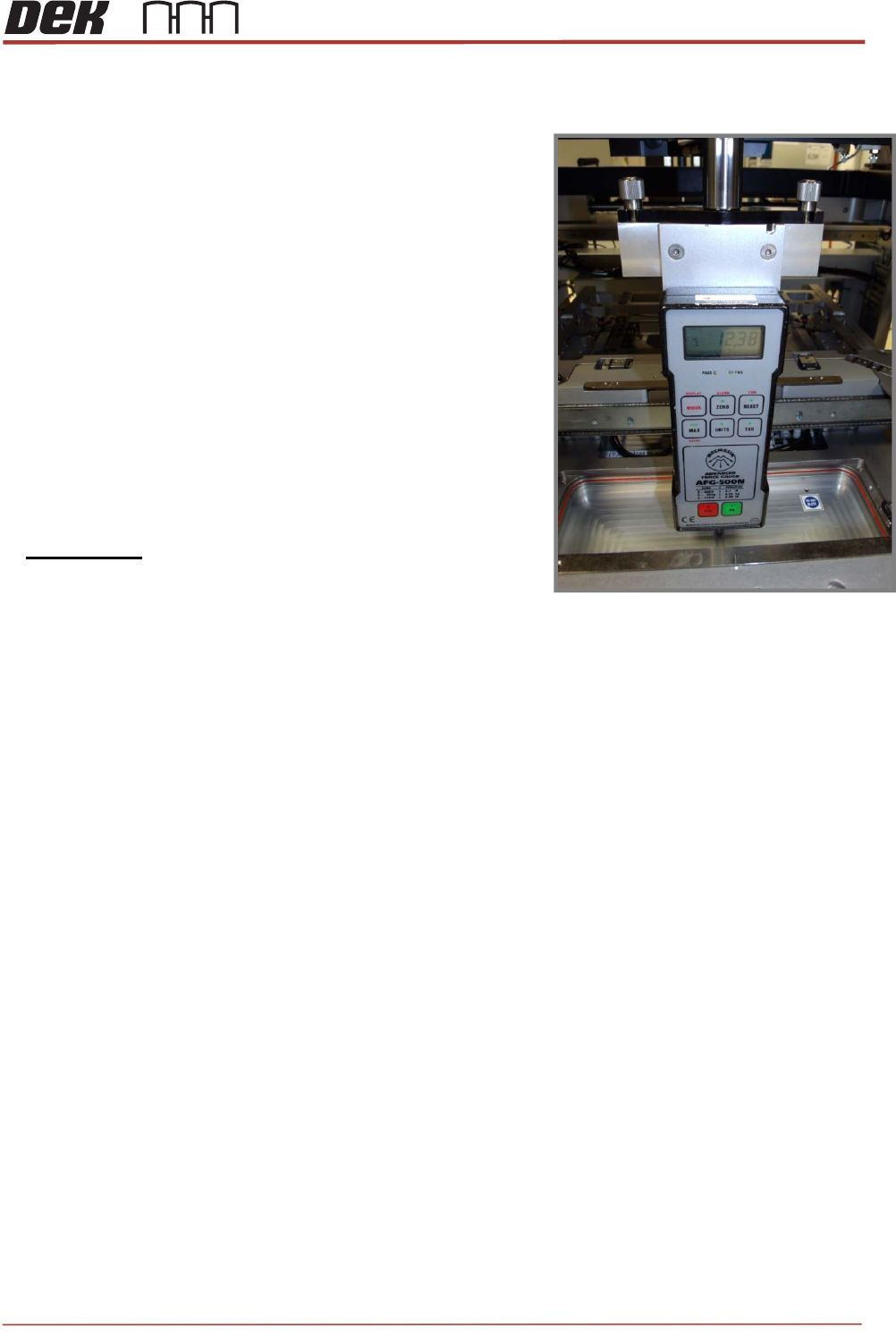
Objective 35: Calibrate Squeegee Pressure
1. If necessary, fully initialise the printer using the BLUE
Button.
2. Enter MAINTENANCE / CALIBRATIONS and select
PRESSURE.
3. Select CALIBRATE READINGS
4. Fit the ‘Squeegee Pressure Rig’ as shown.
NOTE: The pressure calibration feature is machined into
the vacuum pocket of the MEK Base.
5. Follow the standard Calibration Procedure
6. i.e. Use JOG RIG to adjust & obtain a reading of
10kg +/- 0.1 on the Force Meter.
7. Select SET CALIBRATION to save.
8. Remove the Squeegee Pressure Rig.