TRS Advanced WB Intel Issue 02.pdf - 第130页
TRS A 130 V er A im To v To o · · Not e Ma k · ste p · · · · · · are a · cap · · con t c A dvanced M ification o : v erify that a o ls requir e Depth mi c Co-planar e k e sure all Remove a p ) At transp o Apply TR P Driv…

Issue 2, Nov 14
TRS Advanced Maintenance
129
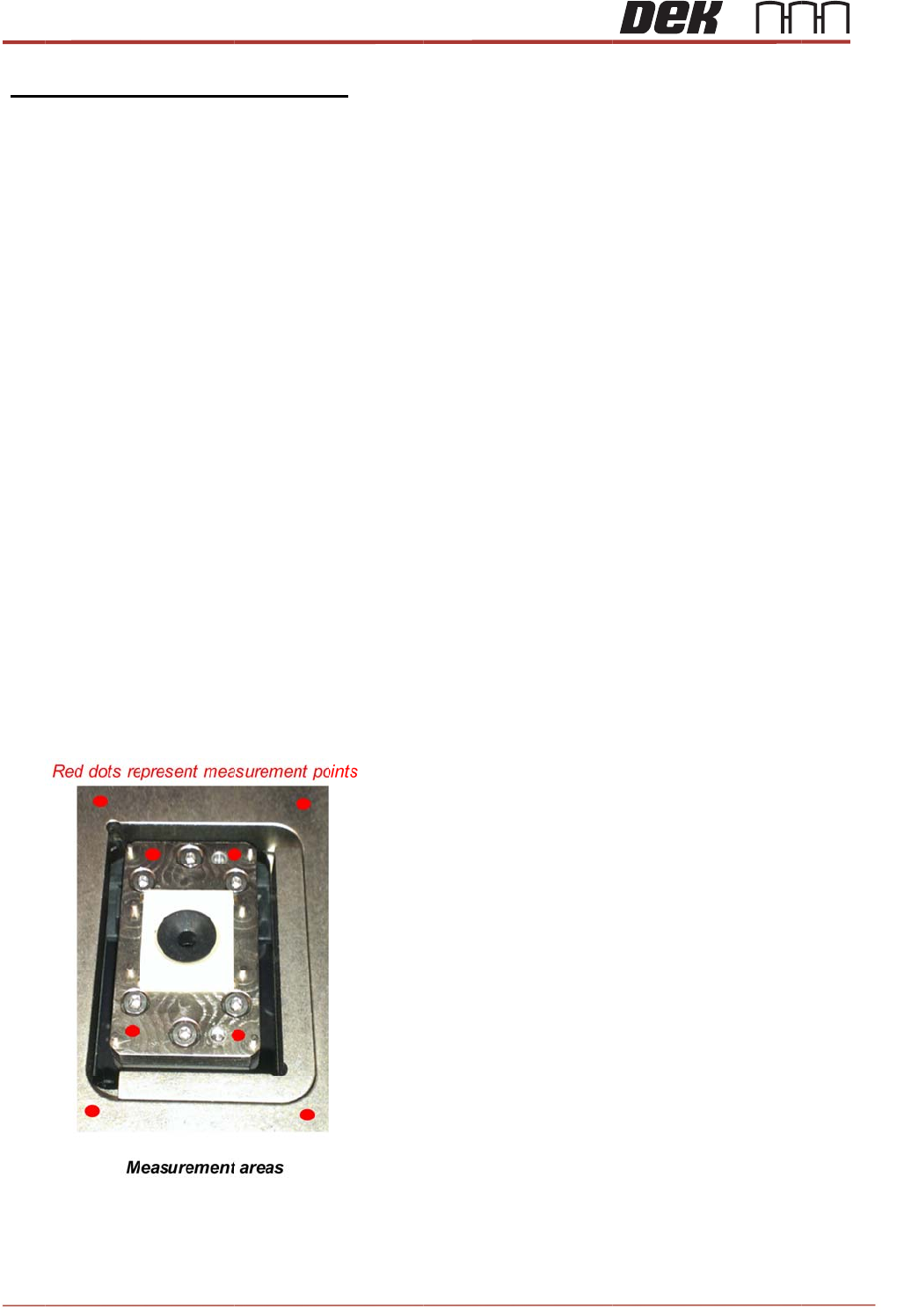
Surround plate setup
Note
setup, soft lift land and pitch adjustment checks must have been completed
before this stage.
• If not already done loosen all fasteners that hold the top and bottom surround plate to the
bearings. (Screw Thread engagement still needed but both plates must be free to move)
• With the TRP in home position and table at transport height
• Load a tray with substrates
• Drive TRP over rails
• Apply TRP pressure
• Toggle vacuum on
• Drive table to Vision height
• Check that the four TRP height adjustment screws are not in contact with the rail cap and
that the TRP is flat against the surround.
• Toggle on the Z lock
• Toggle on the active surround
• Drive TRP to home position
• All substrates should be sat within the surround and surround referencing the substrates into
the top left corner of the top surround plate.
• Using your finger check for movement in all substrates in X and Y direction.
• If any movement is found manual adjustment is needed to the position of the top surround plate.
• After observing the movement in the substrates determine the movement needed in the
to apply equal pressure to the side walls of each substrate in each position.
• With one hand manually apply pressure to the top surround plate moving it in the direction desir
e
• With you other hand check for movement across all substrates and continue to apply
pressure until movement has been removed.
• Visually check that no gaps can be observed between the substrates sidewalls and surround
plates top and bottom
• Whilst still applying force to the top surround plate; In a circular motion tighten all surround
plate screws, this doesn’t need to be over tightened and should be equal to 1.8Nm
TRS
A
130
V
er
A
im
To
v
To
o
·
·
Not
e
Ma
k
·
ste
p
·
·
·
·
·
·
are
a
·
cap
·
·
con
t
c
A
dvanced
M
ification
o
:
v
erify that
a
o
ls requir
e
Depth mi
c
Co-planar
e
k
e sure all
Remove
a
p
)
At transp
o
Apply TR
P
Drive to vi
Toggle Z l
Drive TR
P
Position t
h
a
Using the
.
Complete
If the tow
e
t
rol
c
entre and
M
aintenanc
e
o
f Tower
C
a
ll tower a
e
d
c
rometre
ity bars
tools are
c
a
ny popula
o
rt height
d
P
pressur
e
sion heig
h
ock on
P
to home
p
h
e co-plan
a
depth Mic
the table
b
e
r co-plan
a
log a rep
o
e
C
o-Planari
ssemblies
c
alibrated
ted trays f
r
d
rive TRP
o
e
h
t
p
osition
a
rity bars i
rometre ta
b
elow with
a
rity is fou
n
o
rt for inve
s
ty
are within
r
om the s
y
o
ver rails
p
n the Cha
s
ke readin
g
measure
m
n
d to be o
u
s
tigation
60µm Co
-
y
stem (Su
b
p
osition
s
e over th
e
g
s from fo
u
m
ents
u
t of speci
f
-
planarity
w
b
strates n
o
e
tooling
u
r position
s
f
ication ple
Issu
w
hen inst
a
o
t required
s
around t
h
ase conta
c
u
e 2, Nov 14
a
lled in the
for this
h
e tower
c
t the loca
machine
l service

Issue 2, Nov 14
TRS Advanced Maintenance
131
Vacuum pressure and flow per
tower
Aim:
To Verify/baseline the tooling vacuum capability and flow
capability per tower.
Allowing threshold settings to be defined for the machines warning
systems.
All procedures to be completed using tooling
setup page
· At transport height with tray loaded drive TRP
over rails position
· Apply TRP pressure
· Toggle vacuum on
· Drive to vision height
· Toggle Z lock on
· Drive TRP to home position
· With the Vacuum remaining on remove a substrate from the tooling cap
creating a leak
· Using the vacuum readout on the machine MMI display record the value in
the table below
· Return the substrate to the position it came and record the readout from the machines
MMI Display
in the table below
· Once complete remove three substrates from their tower caps to define the
pre vacuum Threshold
Notes:
There should be more than a 10KPA drop in vacuum pressure when one
substrate has been
removed. This can very dependent on tower cap design but should be
equal to or more than.
If less than 10 KPA drop has been observed please contact your FSE or local
service control centre to
escalate for actions.